3D printer – first test


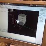
After some initial tuning we did three test-prints today of a 10x10mm square, 30 layers, raising the z-axis by 0.5mm for each layer. We tried to set it up so that when the X or Y-axis moves 10mm, the extruder A-axis should also move 10 units. The way it is set up right now it might be extruding slightly too much plastic per mm. The maximum feedrate we tried was 600mm/min.

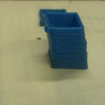
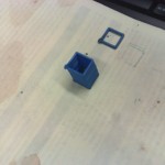
We printed the same geometry three times, here is the second try (in the first try the base/bed wasn't staying very fixed, so the print resembles the leaning tower of Pisa...)

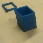
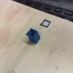
Here is the third try. Now we are moving the Z-axis +0.5 mm during the last Y-axis move. This is at 600mm/min.

We were pretty happy with the print-quality so far, considering this is the first ever test of our extruder/xyz-table setup. Some tuning of how much plastic is extruded for each mm of xyz-feed, and perhaps a heated printing-bed, should improve the quality further. Next is learning to use one of the many STL to G-code CAM programs and filtering the G-code output so it is suitable for our EMC2 setup (the extruder is the A-axis, in absolute mode).

Update: Risto has more on this in his blog: ?http://risto.kurppa.fi/blog/2010/12/first-prints-with-reprap-the-open-source-3d-printer/

Temperature PID control

We hooked up the temperature measurement circuit and the PWM-amplifier to EMC today and tested PID-control of the extruder head temperature. The ini, hal, and xml files for this are here: temp_control_pid.tar

It's probably much easier to figure out the connections from the diagram below than to browse the text files. The square wave, which has a frequency proportional to the temperature, comes in on parallel port pin-13, and is connected to an encoder. The encoder has a velocity output which will be equal to the frequency of the square wave in Hz. This frequency is used as the feedback for a PID-component which compares the measured frequency against a set-point which is taken from a pyvcp slider. The pid output is used as an input to a pwm-generator, whose output needs an inverter, since the pwm-amplifier is active-low. The PWM is output on parallel port pin 9.

I wish there was a tool which would draw these HAL/pyVCP diagrams automagically from the source files. There is some work in that direction already: crapahalic and HAL with gschem.

EMC2 upgrade

I've upgraded Ubuntu and EMC2 on the Atom 330 machine I have for controlling the lathe. The Atom 330 is a dual-core chip, but with Hyper Threading the OS can see four cores. That's not good for real-time performance, so the first thing I did was turn off HT from the BIOS. Next I did a distribution upgrade to 10.04LTS which downloaded about 1 Gig in an estimated 9 minutes (2Mb/s is OK I guess...). I then used the emc2-install script which installs the real-time kernel and emc2, and finally I edited /boot/grub/menu.lst by adding "isolcpus=1" on the kernel line. This reserves one cpu core for real-time and the other for non-real-time tasks. Without "isolcpus=1" the latency-test jitter values were easily 10k and more with a light load on the machine. With one core dedicated to real-time the jitter numbers start out at around 4k at light load and double to 7-8k under heavy load.

Here are some selected screenshots:

Next stop is getting the X and Z servos moving, as well as the hefty 2 kW spindle servo.

EMC and EMC2 references

Someone created a wikipedia page for EMC over here: http://en.wikipedia.org/wiki/Enhanced_Machine_Controller

The wikipedia-police have immediately put it on the list of pages to be deleted ("unremarkable", "no third party references", "borderline advert", etc.). So I decided to collect some references. It is best to archive them here also, in case the wikipedia page does get deleted.

There should be a report by Rogier Blom called roughly "Design and development of a real time trajectory planner for the Enhanced Machine Controller", but I wasn't able to find that. It's probably the same document as this one (the pdf has chapter 4->): http://emc.cvs.sourceforge.net/viewvc/emc/emc/doc/segmentqueue.pdf?view=log

Please comment below and/or enhance the wikipedia article if you find more references!

  • Proctor, F. M., and Michaloski, J., "Enhanced Machine Controller Architecture Overview," NIST Internal Report 5331, December 1993. Available online at ftp://129.6.13.104/pub/NISTIR_5331.pdf
  • Albus, J.S., Lumia, R., “The Enhanced Machine Controller (EMC): An Open Architecture Controller for Machine Tools,” Journal of Manufacturing Review, Vol. 7, No. 3, pp. 278-280, September 1994.
  • Fred Proctor, John Michaloski, Will Shackleford, and Sandor Szabo, "Validation of Standard Interfaces for Machine Control", Intelligent Automation and Soft Computing: Trends in Research, Development, and Applications, Volume 2, TSI Press, Albuquerque, NM, 1996, http://www.isd.mel.nist.gov/documents/proctor/isram96/isram96.html
  • Leto et al., "CAD/CAM INTEGRATION FOR NURBS PATH INTERPOLATION ON PC BASED REAL-TIME NUMERICAL CONTROL", 8th INTERNATIONAL CONFERENCE ON ADVANCED MANUFACTURING SYSTEMS AND TECHNOLOGY JUNE 12-13, 2008 UNIVERSITY OF UDINE - ITALY, http://158.110.28.100/amst08/papers/art837759.pdf
  • Glavonjic et al., "Desktop 3-axis parallel kinematic milling machine", The International Journal of Advanced Manufacturing Technology Volume 46, Numbers 1-4, 51-60 (2009), http://dx.doi.org/10.1007/s00170-009-2070-3
  • Milutinovic et al., "Reconfigurable robotic machining system controlled and programmed in a machine tool manner", The International Journal of Advanced Manufacturing Technology, 2010, http://dx.doi.org/10.1007/s00170-010-2888-8

Mesa 5i20 breakout boards

In 2006 I made optoisolator cards for the cnc-mill project, but now with the lathe I am using servo-drives and a VFD which mostly already have optoisolated inputs, so I will use these very simple breakout boards instead. There are two pitch-standards for the screw-terminals, an imperial one with a pitch of 5.08 mm (i.e. 0.2 inches), and a metric one with 5.0 mm pitch. These boards are for 5.0 mm.

Pads logic and layout files: 2010_01_16_m5i20_breakout_board

Etch-mask (PDF): etch-mask


EMC2 test run

The servos are now almost ready to go on the mill. Some dry-running of EMC2, the servo electronics, and the VFD today. I've made this pyVCP panel for AXIS which displays the commanded and actual spindle RPM, the spindle current (in some uncalibrated unit), the PID outputs and following errors for X/Y/Z. The jog-pendant box shows the mode of the jogwheel (X-jog, Y-jog, Z-jog, Off, Feed-override, Spindle-override), and the jog-increment (0.01 mm above). The four pendant buttons are now wired to turn on/off the coolant (blue button), to start the spindle forward or stop it (yellow button), to step through the program (green button), and to pause/resume the program (red button).

A video of the setup.
0:00 Actors, in order of appearance: EMC2, jog-pendant, electronics box, limit-switch box, X/Y/Z servos, VFD, Spindle motor.
0:30 Running a program. Load-meters. Rotating servos. Rotating spindle. Note professional mount and axis-coupler for spindle-encoder. The encoder will eventually be mounted on the other end of the motor.
1:30 Load-monitor demonstration. Running the machine from (300,300,300) to (0,0,0) with a rapid move (6000mm/min or around 2400 RPM on the servo shaft) and watching the bar-graphs show the commanded PWM to the amps.

It's best to store all the working config files here in case of disk crashes or other data loss: