Jari shot some videos during the milling of the beaver-tail bulb. They now appear on YouTube.
For a mostly home-built cnc minimill of this size, this is pretty 'hard core' stuff...
Jari shot some videos during the milling of the beaver-tail bulb. They now appear on YouTube.
For a mostly home-built cnc minimill of this size, this is pretty 'hard core' stuff...
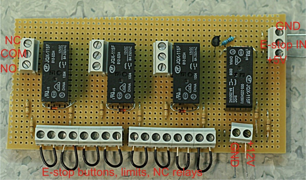
This is the E-stop circuit I am going to use when upgrading the cnc-mill to servo control. The idea is to use a wire-OR circuit (series connection of NC switches) for things that cause an E-stop followed by a wire-AND circuit (parallel connection of relays) for things I want to happen at E-stop.
The E-stop out signal from EMC is wired to the top right of this board (labeled E-stop IN...). When this signal goes high it closes the rightmost relay which has +12V wired to it. The 12 V then goes through a series of NC switches, which I've here just shorted out with the black wires. In reality the black wires will be replaced by one E-stop button on the main enclosure, one E-stop button on the jog-pendant, X/Y/Z limit switches, NC servo-amp fault relays, and a VFD NC fault relay.
When all is well +12 V is supplied to the three other relays, and these provide NC or NO outputs. One is used to tell EMC everything is OK (E-stop IN signal in EMC), one is used to enable the power switch of the axis servos, and one is spare for now.
This should make the machine reasonably safe. If any of the E-stop buttons are pressed, a limit is tripped, or the servo amps/VFD are not feeling well we should go into E-stop, and that will cut power from the servos. EMC will also notice this and I'm relying on EMC to shut down the coolant pump and the VFD.
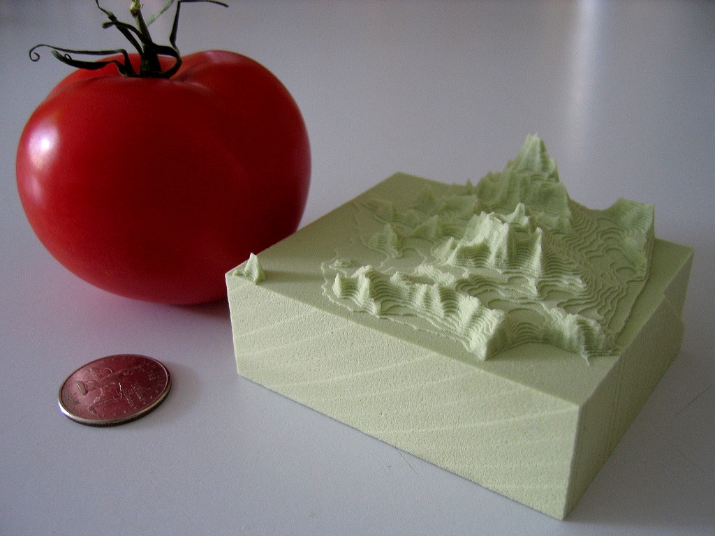
Dan Egnor sent me this nice example of bitmap-based toolpath generation, or 'pixel mowing'. It's a slightly exaggerated topographic relief of San Francisco machined in tooling board using a very simple 'lawn mowing' toolpath generator.
The explanation of how it works below is mostly Dan's, not mine.

This is the input to the toolpath generator for one of the Z-slices.
black - material which must not be touched
green - to be removed, is safe (at least one tool radius from black)
yellow - remove if possible, is dangerous (within tool radius of black)
purple - has been cleared, is dangerous (machine limits or similar)
white - has been cleared, is safe, is not blue (below)
blue - this spot has been cleared, and is safe, but is within one tool radius of material that needs clearing (green or yellow)
Note that you don't see blue in either "before" or "after" images, it only occurs transiently. (In theory it could show up in "before" as area outside the workpiece.)
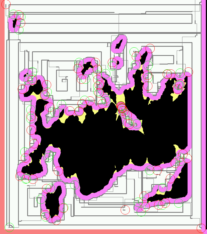
And this is the resulting toolpath. Green circles are plunges and red circles are lifts. The thick grey lines represent actual cuts, the thinner lines are rapid feeds.
The basic rule is that the tool *centroid* is only allowed to visit safe areas (green, blue, and white). Green and blue represent work to be done (safe areas that need visiting). Of course, as the tool moves, green changes to blue and white, and (some) yellow changes to purple.
The real trick is in efficiently tracking the "within tool radius of" zones (material to be cut, or material to stay away from). Every pixel keeps a count of how many pixels of each type ("nearby-blocking" or "nearby-cutting") are within one tool radius of that pixel. Whenever a value is changed ( e.g. the simulated tool moves and changes some points from "cut" to "clear"), every counter within the appropriate radius is updated.
That would be rather costly to implement directly, each simulated pixel move would require N^3 updates, if N is the diameter of the tool. Instead those counters are only kept as *differences* between each point and its neighbours. That means changing a point only requires updating the values along the *perimeter* of the radius surrounding that point, meaning that a simulated pixel move only requires N^2 updates, which makes things a lot more tractable (though it still takes the old laptop I use a couple minutes to complete the toolpaths for a 5" x 3" x 1.5" model at 1/256" resolution). Of course this means that the "color state" isn't directly accessible for a random pixel, but must be figured incrementally from neighboring values. Fortunately most operations don't access random pixels.
You would probably not want to cut metal with this kind of algorithm as there is no control over material removal rate or cutting forces, but for foam, tooling-board, or wood it should work ok.
Dan's program is written in C++ and available here (http://svn.ofb.net/svn/egnor/boring/), but it's not well documented.
We are standing by for a video of this kind of cutting!
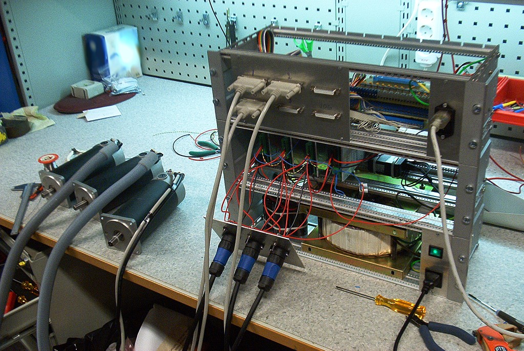
Some good steps towards driving our cnc-mill with DC-servos taken today. I got the pico-systems servodrives wired correctly, the new 50 kHz PWM m5i20 configuration loaded onto the fpga, and updated my pyvcp test panel a bit. I'm using three 19" rack enclosures. The lower one has a 1.8 kVA transformer, the middle one houses the servodrives, and the top one has differential encoder cards for the motors and optoisolator interfaces to the m5i20.
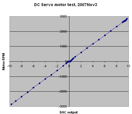
One small setback was that the servodrives wanted the PWM in reverse polarity compared to what I had available. There's nothing in the m5i20 driver to reverse the polarity of the DAC output PWM. Fortunately the drives have optocoupler inputs so instead of GND-PWM I wired them in a PWM-Vcc configuration and it worked OK. I did an open-loop no load test (below) where I monitored the RPM while changing the DAC output. There's a bit of dead-band in the middle where nothing happens between DAC values of about -0.2 and +0.2. After that the curve is pretty linear up to +9.7 after which the PWM pulse becomes unacceptably short for the servodrive and at DAC=9.8 or above the motors just jump and stutter. So eventually with EMC and PID control I need to limit the DAC range to [-9.7 , +9.7].
Next is probably trying out closed-loop PID control, and after that I need to look at the E-stop chain, home switches, a relay for the flood coolant pump, and controlling the VFD/Spindle.
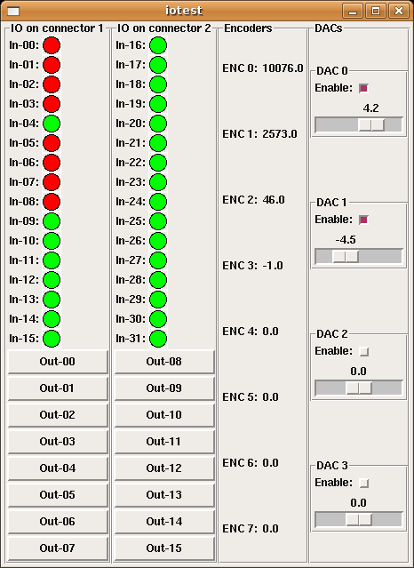
For testing the servo-drives and all the electronics I found this test-panel for the HOSTMOT-4 conifiguration of the m5i20 quite useful.
It uses an XML file (iotest.xml) to define the pyVCP panel layout, and then a HAL file (pyiotest.hal) to hook up the IO pins of the m5i20 to the panel. I'm also using a shell script (iotest.sh) to start the realtime environment and run pyvcp followed by the HAL file automatically.
Compare this to my earler effort with the old VCP. Now with many more widgets in pyVCP I have better control of the DACs etc.
Stuart Stevenson wrote about his Dah-Lih EMC2 conversion on the emc-mailinglist, and has allowed me to publish these pictures of his mill. I've scaled the pictures to 1024 pixels wide - click the picture to see it in high-resolution.
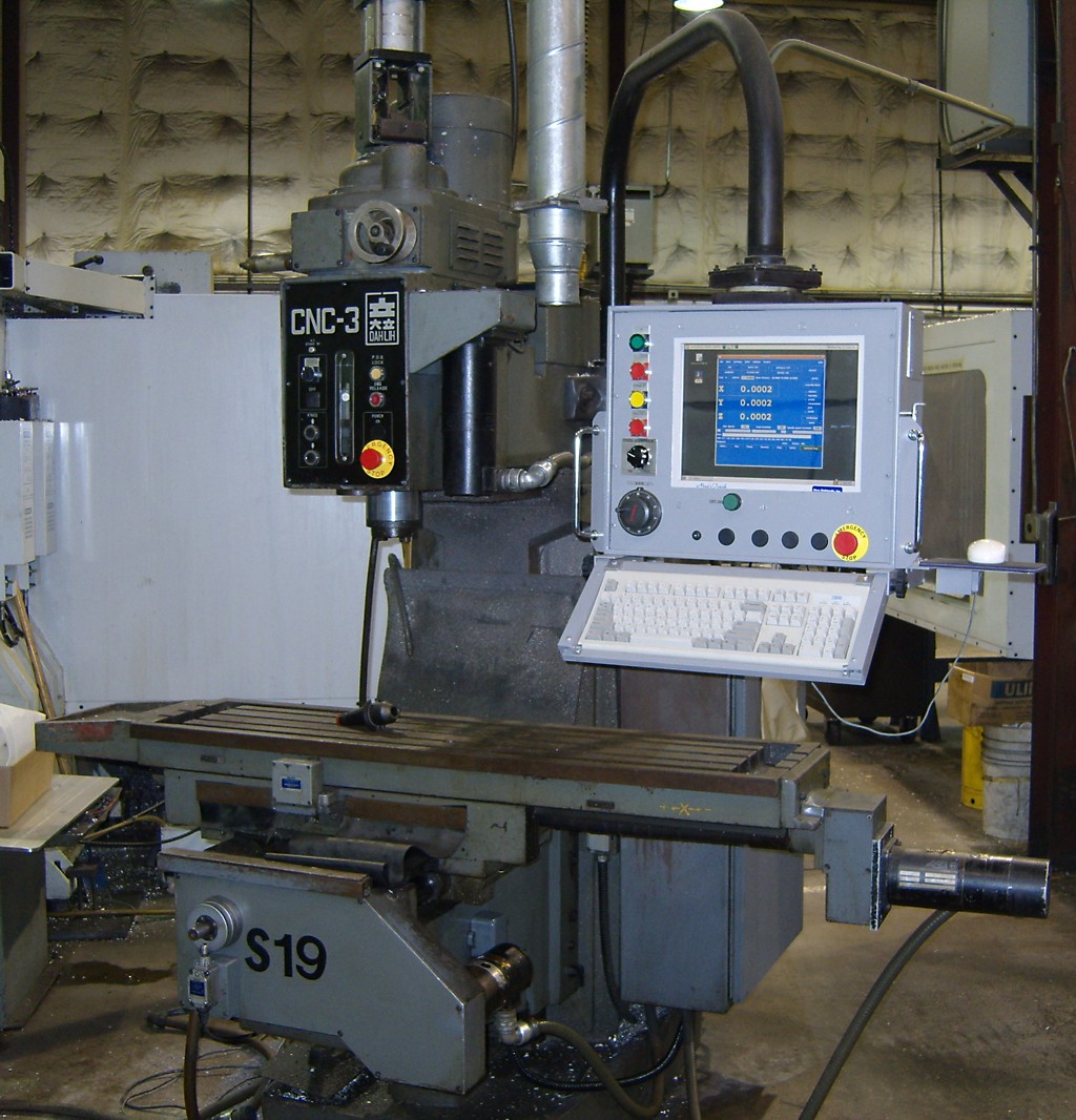
Machine after conversion.

Machine before conversion. Pendant has original CRT and buttons.
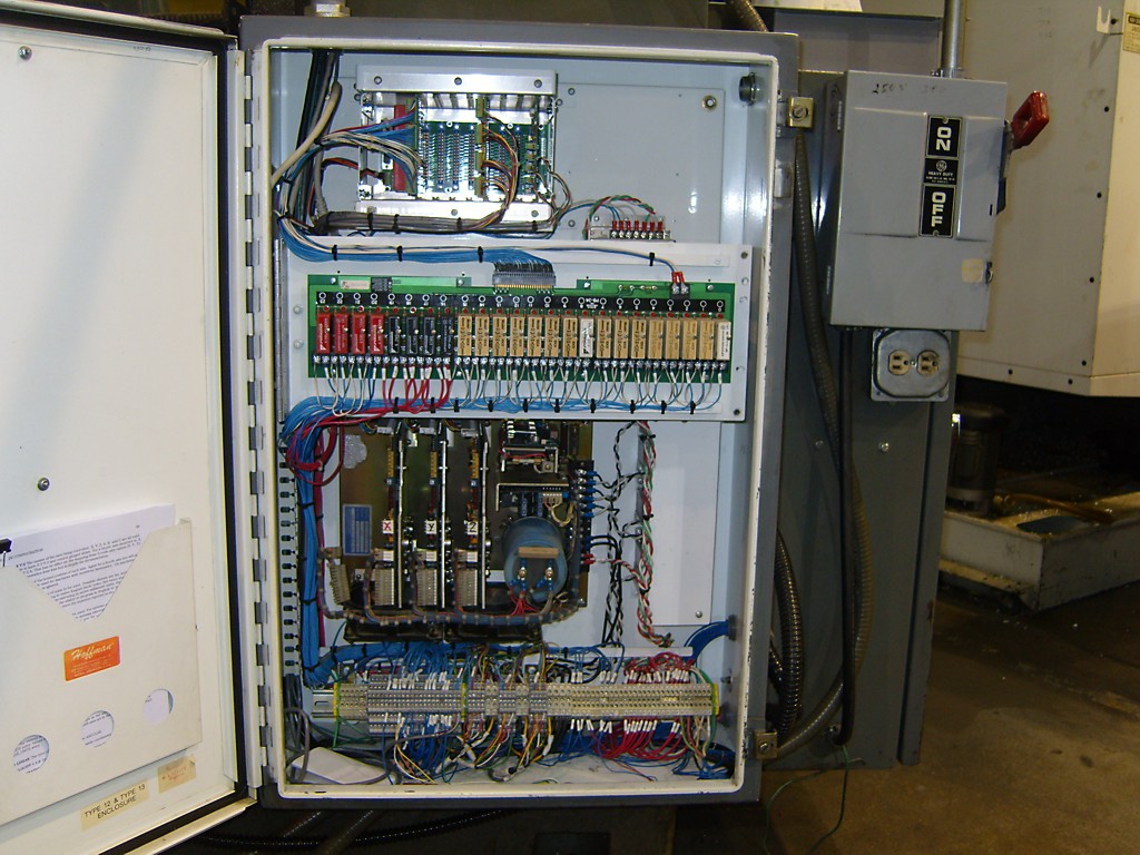
Control electronics. Jon Elson's PPMC cards at the top.
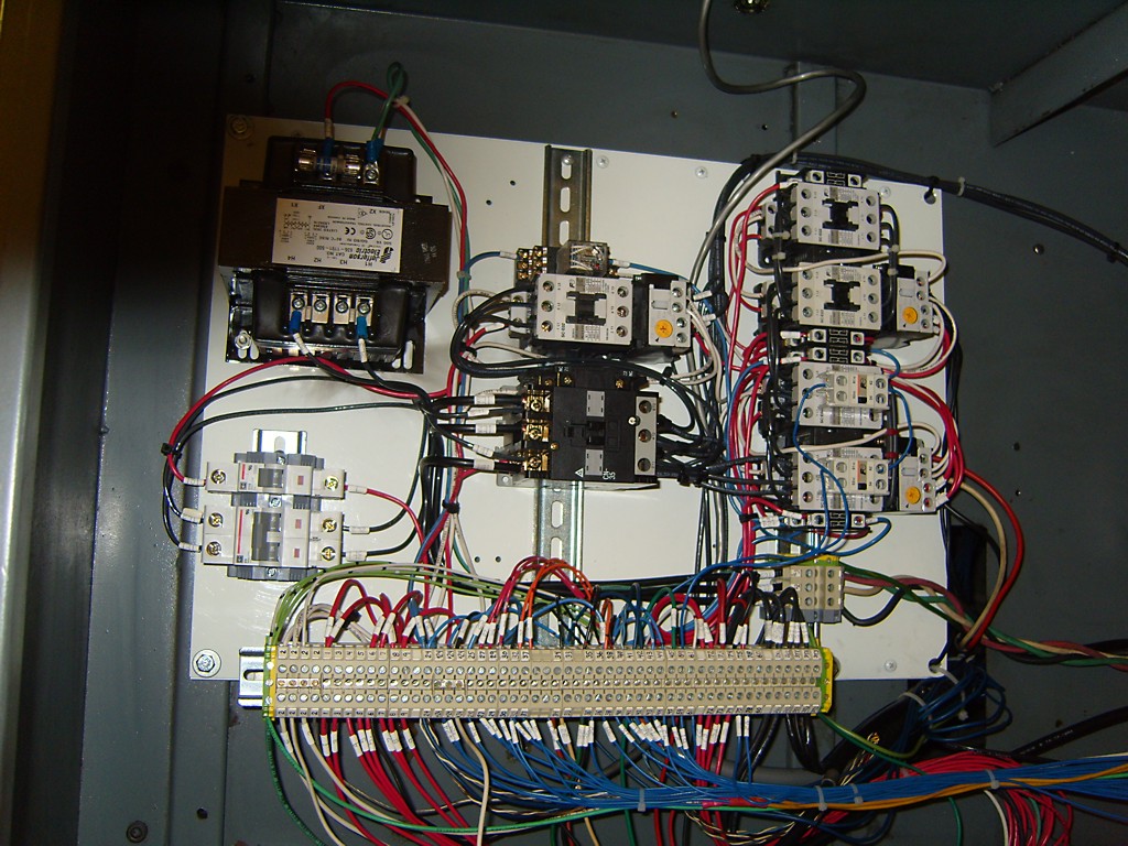
Relays and transformers.
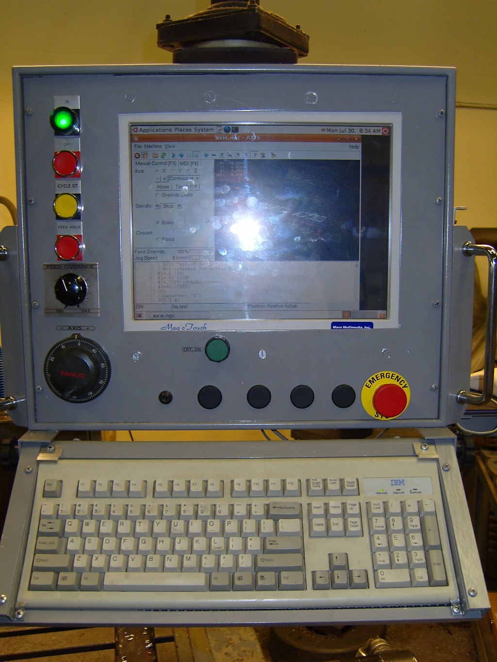
The new control. The computer is a Gateway Profile 3.
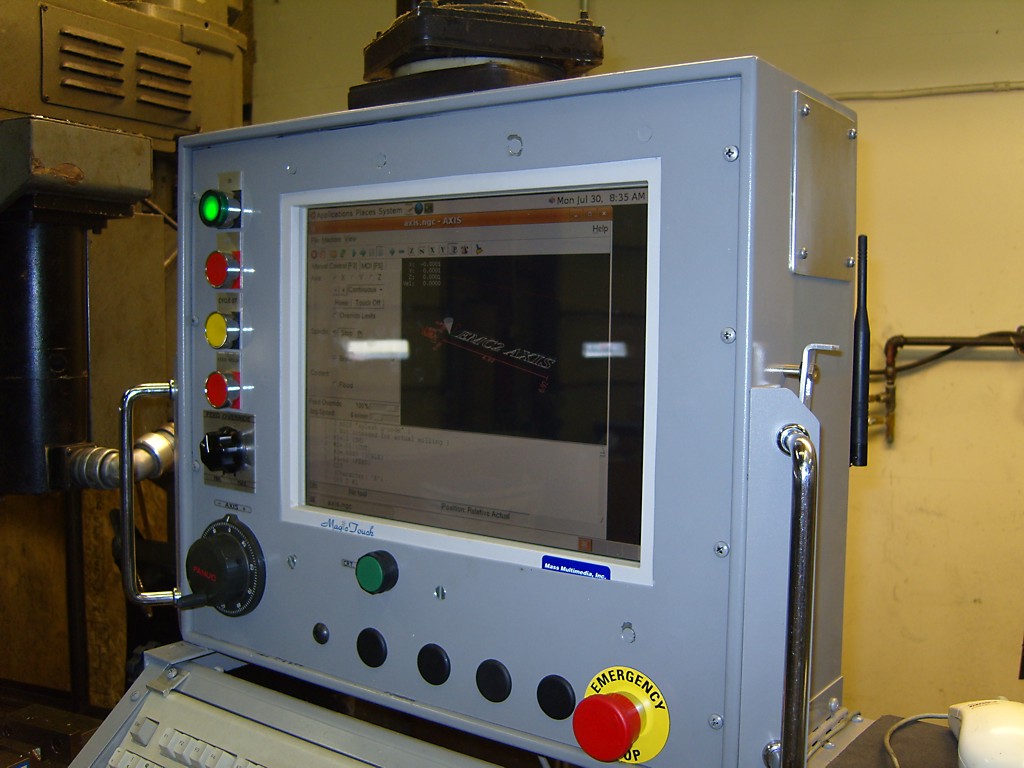
There is a MagicTouch touch screen mounted in front of the computer.
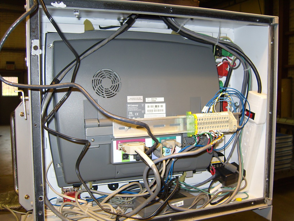
Back side of control. The computer is connected to the PPMC cards by the parallel port only. Jog-wheel and buttons are wired directly to PPMC. The network cable goes to a Linksys WET11 bridge mounted on the back panel.
Jari upgraded the spindle motor to 1.5 kW and shot a few more milling videos.
movie 1:
movie 2:
movie 3:
movie 4:
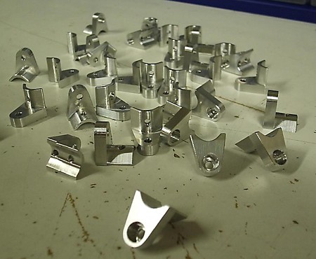
Finished parts:
There was something strange going on when I measured the transformer last time, and since that I've gotten a few pointers from visitors to the blog and the CAD_CAM_EDM_DRO list.
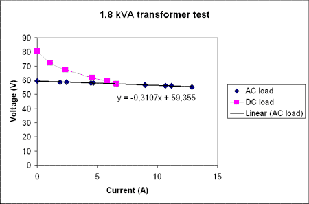
I now did a test without the inrush current-limiter, and it does make a difference. It is rated for 8 A continuous current, but apparently it limits current much before that...
Now the 'AC load' line is measured by hooking up resistive loads to the secondary windings (no rectifier or caps), and it shows a series resistance of about 0.3 Ohms, or similar to what can be measured with a multimeter over the secondary windings. So at least the transformer seems to be working.
Then I hook up the secondary to the diode bridge and the caps and connect the same set of resistive loads as before. That's the 'DC load' measurements above. There again I see a big drop in voltage at first that then levels off somewhat. For the points above 5 A current the voltage drop is around 2 V per amp, or about a 2 Ohm effective series resistance. Also, the transformer does not emit any sound at all during the AC test, but now with the rectifier and caps when I load it up there is a slight 'humm' sound(probably 50 Hz and its harmonics).
I wonder if that 2 Ohm is typical or if there still is something strange going on? (could the rectifier bridge be too small? Anything wrong with my 4x 10 000 uF 100 V electrolytic caps?)
I tested this with one bridge rectifier GBPC5004 rated at 400V/50A and another one, a GBPC5010 rated 1000V/50A, but the results are the same. Looking with an oscilloscope at 6 A load at the DC voltage there is about 1.4 V of ripple.
Jari has made an enclosure around our cnc-mill, and that allows us to use a liberal amount of flood coolant. Here's a short video with some tests in aluminium.
Before you run to the shop and get an Opti-BF20 of your own please remember that our machine is seriously modified. We put a new table on it with linear guides, we're using ballscrews, and the stock spindle and spindle motor are replaced.