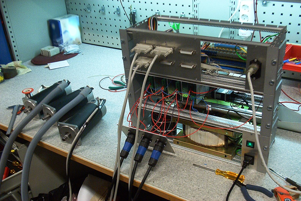
Some good steps towards driving our cnc-mill with DC-servos taken today. I got the pico-systems servodrives wired correctly, the new 50 kHz PWM m5i20 configuration loaded onto the fpga, and updated my pyvcp test panel a bit. I'm using three 19" rack enclosures. The lower one has a 1.8 kVA transformer, the middle one houses the servodrives, and the top one has differential encoder cards for the motors and optoisolator interfaces to the m5i20.
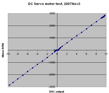
One small setback was that the servodrives wanted the PWM in reverse polarity compared to what I had available. There's nothing in the m5i20 driver to reverse the polarity of the DAC output PWM. Fortunately the drives have optocoupler inputs so instead of GND-PWM I wired them in a PWM-Vcc configuration and it worked OK. I did an open-loop no load test (below) where I monitored the RPM while changing the DAC output. There's a bit of dead-band in the middle where nothing happens between DAC values of about -0.2 and +0.2. After that the curve is pretty linear up to +9.7 after which the PWM pulse becomes unacceptably short for the servodrive and at DAC=9.8 or above the motors just jump and stutter. So eventually with EMC and PID control I need to limit the DAC range to [-9.7 , +9.7].
Next is probably trying out closed-loop PID control, and after that I need to look at the E-stop chain, home switches, a relay for the flood coolant pump, and controlling the VFD/Spindle.
A question by email on how I got the m5i20 FPGA configured for 50 kHz PWM output. My reply:
The "normal" FPGA config that you get with the m5i20 driver by specifying loadFpga=1 in your HAL file is the Hostmot-4 config with maximum PWM rate of 32 kHz.
If you have the standard amp from Jon it wants a 50 kHz PWM signal.
You can load an FPGA config that goes up to 100 kHz PWM by following the instructions in the Readme here:
http://cvs.linuxcnc.org/cvs/emc2/src/hal/drivers/m5i20/
(or emc2/src/hal/drivers/m5i20/ on your local install)
basically you load the config with
m5i20cfg hostmot5_4eh.bit 0
you need to be in the directory with the bit files when you do that:
emc2/src/hal/drivers/m5i20/bit/
remember now when you load the m5i20 driver from your HAL file you should specify loadFpga=0, otherwise you overwrite the FPGA with the 32kHz config again.
The m5i20 has not been updated for the 100 kHz PWM bit files, so the timing information you specify is in a slightly weird format. Basically as the old bit-file assumed a 33 MHz PWM clock and accepted the PWM rate as an integer between 0 and 32000, now that we have a PWM clock of 100 MHz everything is going to get multiplied by three, so to get the 50 kHz PWM you want you need to specify dacRate=16666
hope this helps,
Anders
The deadband is probably caused by MOSFET deadtimes which causes crossover distiortion.
This actually happens at the point where motor current crosses zero, not at voltage zero. So if you have running motor and start reversing direction, you get distortion in different place of curve.