PI-Controller

I made this PCB on the LPKF mill today:

pi_pcb pi_pcb_backside

Moments later, it was populated with components:

pi_pcb_components

This is a PI-controller with three op-amps. One for the P-term, one for the I-term, and one that sums P+I.

The left side of the PCB is a +/-12V power-supply consisting of a DC2DC converter, caps and EMI-filters (Murata NFE61), LM337/LM317 adjustable voltage regulators, and more caps and EMI-filters. Despite the caps and filters I'm not sure this design gives good enough +/- 12V DC supplies for instrumentation use - when the DC2DC input comes from a typical cheap "wall-wart" switch-mode PSU. Or perhaps there is direct RF/capacitive cross-talk from the wall-wart input to the op-amp circuits which shows up as noise in the signal?

The PCB is shaped to fit a Fibox enclosure.

Attenuator

"Attenuator" is just a fancy word for voltage divider. This hack will not win many points for beauty:
attenuator_1
Enclosed in a box it looks nicer 🙂
attenuator_2

This attenuator goes between two op-amp circuits where I figured the first circuit will be able to drive a 10 kOhm load, and the input impedance of the second circuit is high enough not to load the voltage divider too much.

The back-of-the envelope design called for six voltage dividers with log-spaced attenuation between -6 dB and -40 dB. The input and output are connected to a 2-pole 6-position rotary switch that selects which voltage-divider is in use. The measured attenuation differs from the design by about 0.5 dB at most. For a large input-signal at the -6 dB attenuation setting the -3 dB bandwidth is about 600 kHz.

Design spreadsheet:
attenuator_design

A second photodiode amplifier PCB

I made this PCB for a second photodiode amplifier today. This one is designed for higher light-levels and higher bandwidth. I will post the schematics along with measurement data when I've tested the circuit.

beat_amp_pcb_bottom beat_amp_pcb_top

The V-cutter is designed to cut a slot that is nominally 8 mils (0.2 mm) wide, but the actual cut-width depends on how the z-axis is adjusted. Removing the ground-plane copper from under the high-speed op-amps is supposed to minimize stray capacitance.

PCB Milling

I'm making photodiode (transmipedance) amplifiers, and here is the first PCB being milled today. In the foreground a test-run where the cutter-height was too low resulting in too thin or vanishing PCB-traces. Note how the PCB material is not held in place along the Z-axis at all. The PCB-blank is just located in X/Y on the table using two locating pins/holes. In the Z-direction the idea is that the pneumatic cylinder pushes the lower flange of the spindle into contact with the PCB-material, and the exact cutter-height is adjusted relative to this flange only.

The toolchain is (old!) commercial software: PADS PowerLogic for schematic design, PADS PowerPCB for PCB-design, CircuitCam for converting the gerbers to HPGL, which BoardMaster uses to drive the mill (over RS232).

pd_amp_pcb_top pd_amp_pcb_bottom

For general purpose 3D CAD at work we have Vertex (a Finnish Inventor/SolidWorks clone) and I used it to draw a model of the amplifier:
pd_amp_assembly pd_amp_exploded

The size of the PCB and enclosure is mostly limited by how much of the powersupply one wants on-board, and how big connectors one wants to use. I'm using a standard BNC connector (SMA would have been smaller). The board is powered by a +9...18VDC supply which is DC2DC converted into +/-12 V and then regulated to +/- 5 V for the op-amp circuit. The box at the front is an RF shield for the amplifier itself. Light enters through an 8 mm hole in the face-plate and hits a TO-18 mounted photodiode. More on the circuit later.

The enclosure is 48 mm in diameter with a 16 mm thick face-plate, a 4 mm thick back-plate, and the body (55 mm length) bored out to an inner-diameter of 34 mm. The body should fit a 25x54mm PCB. The end-plates are attached to the body with five M3 screws on a 40 mm diameter bolt-circle. There is an M6 thread on the bottom of the face-plate, for attaching the amplifier to an optical-table or other instrumentation. I made two of these from 50 mm aluminium round-bar on a manual lathe and mill (using a rotary table for the holes/threads).

pd_amp_enclosure

Note: for manual machining five evenly spaced holes the angle-sequence is: 0 - 72 - 144 - 216 - 288 - 0.

I'm thinking about polishing these a bit and then anodizing them. But for RF-shielding the contact-surfaces of all three parts would then have to be sanded/milled-down after andoizing. to ensure good electrical conductivity between the parts.

LPKF Protomat S91 PCB-mill

Update: here's a picture of how the original spindle looks like.
lpkf_protomoat_original_spindle

By popular demand, some pictures of the modified LPKF Protomat S91 PCB-mill (featured here). The spindle assembly on this mill has been re-built. The original has an LPKF spindle motor and a solenoid for pushing/pulling the spindle up/down along the Z-axis. This modification uses a Proxxon spindle and an air-cylinder for the Z-movement.

overview 

overview2

These two pictures shows the spindle from the front. Pressurized air is input to the valve which routes it either to output A or B. This pushes the air cylinder either to the UP or DOWN position. The cylinder pushes on an aluminium plate to which the spindle motor is attached. The moving plate is guided by a linear bearing. A screw at the top of the linear bearing allows adjustment of the Z-depth of the DOWN position. A spring at the top also helps with pushing up the spindle.

cutter


This picture shows the cutter. A vacuum cleaner attaches to they grey tube, and sucks away all chips produced during drilling and milling. A cylindrical cover or "door" around the spindle (now open for tool change) is rotated shut when the machine runs.


connections

This shows the electrical connections. The modification of the spindle involves connecting a cable from the second connector from the right to a custom-built relay box. Otherwise the connections are as on a standard machine.

relay_box


This shows the relay box. The cable from the base of the machine is used to control three On/Off devices: vacuum-cleaner on/off, spindle-motor on/off, and Z-axis up/down. The spindle-motor and vacuum cleaner connect to standard AC-mains sockets. The Z-axis up/down control signal is connected to the air-valve on the spindle assembly.

spindle
up_down

Some additional views. Note how small the required Z-movement is.

z-cylinder
z-cylinder2

These pictures show the air-cylinder.


40-pin breakout board

Making break-out boards is not exactly rocket science... Oh well, this one is required for a 10-channel temperature measurement which we do with pt100 sensors and a 4-wire multimeter. It's great however to have a working toolchain where you come up with an idea in the morning, spend a few hours designing the schematic and PCB, then go over to the PCB-mill and run the CAM-programs to produce the PCB, and assemble and test your circuit by the end of the day.

Ambit vs. 910xt GPS comparison

A couple of screenshots from google-earth. These are GPX files exported from my own Garmin 910xt and my friend's Suunto Ambit.


The 910xt was set on "smart recording", while the Ambit was set to record every second. Both watches are quite confused in tunnels or under bridges. It's clear that the garmin-trace is somehow filtered. A better comparison would perhaps be to set the 910xt also on 1s-interval recording.

UV LED Lamp


We use Norland Optical Adhesive (NOA-81) for gluing bits and pieces together in the lab. The glue cures in UV-light. So far we've used a fluorescent solarium lamp for this, but we broke one of the two remaining lamps and can't seem to source new ones.


So I decided to try an LED solution. These are LEDEngin LZ1-10U600 LEDs with a center wavelength of 365 nm, 28 euros each from Mouser. They are glued to an aluminium plate using a heat-conducting glue, Loctite Output 384:

For simplicity I used a LighTech 18 W 700 mA constant-current powersupply that runs directly off AC mains. The powersupply has a maximum output voltage of 24 V which is enough to drive the five UV-LEDs in series (the UV-LED has a voltage-drop of 4.1 V)

Here's how the lamp looks like:

Most of the blue in this picture is fluorescence from the white paper underneath the lamp. A quick test shows that the NOA-81 glue cures very quickly indeed (seconds) with this lamp. Much faster than with the old fluorescent lamp (minutes) anyway. This kind of lamp may be useful for PCB-making also? I didn't keep the lamp on for very long yet, so I don't know how adequate the alu-plate is as a heat-sink.

Warning: The UV-light from these LEDs may be more or less harmful for your eyes and/or skin. Don't try this at home unless you know what you are doing!

Colorhug build

The other parts for a Colorhug already arrived, and we got the missing color sensor TCS3200D, from Mouser last week.

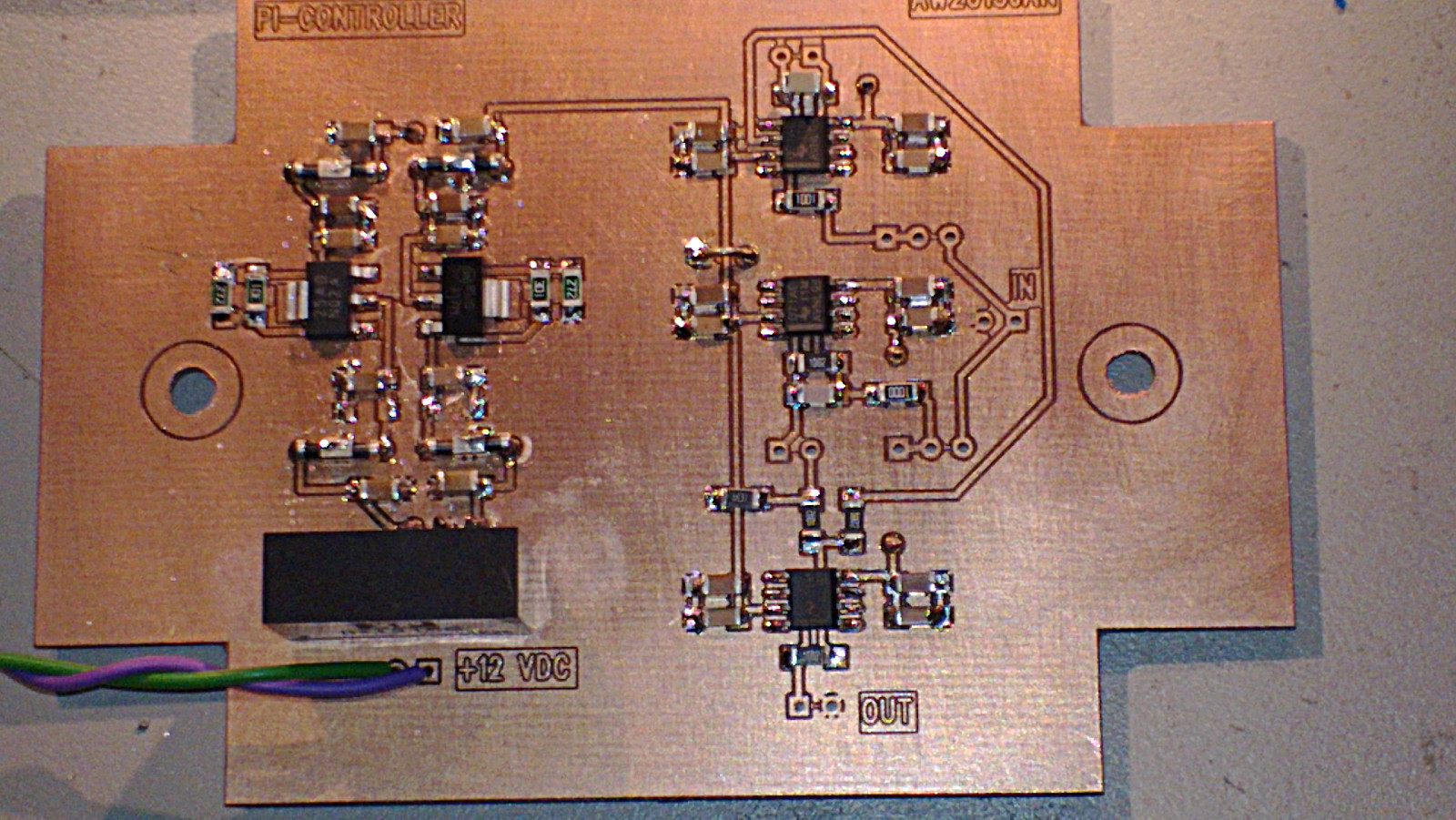
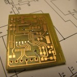
Please don't laugh at my SMD soldering skills 🙂

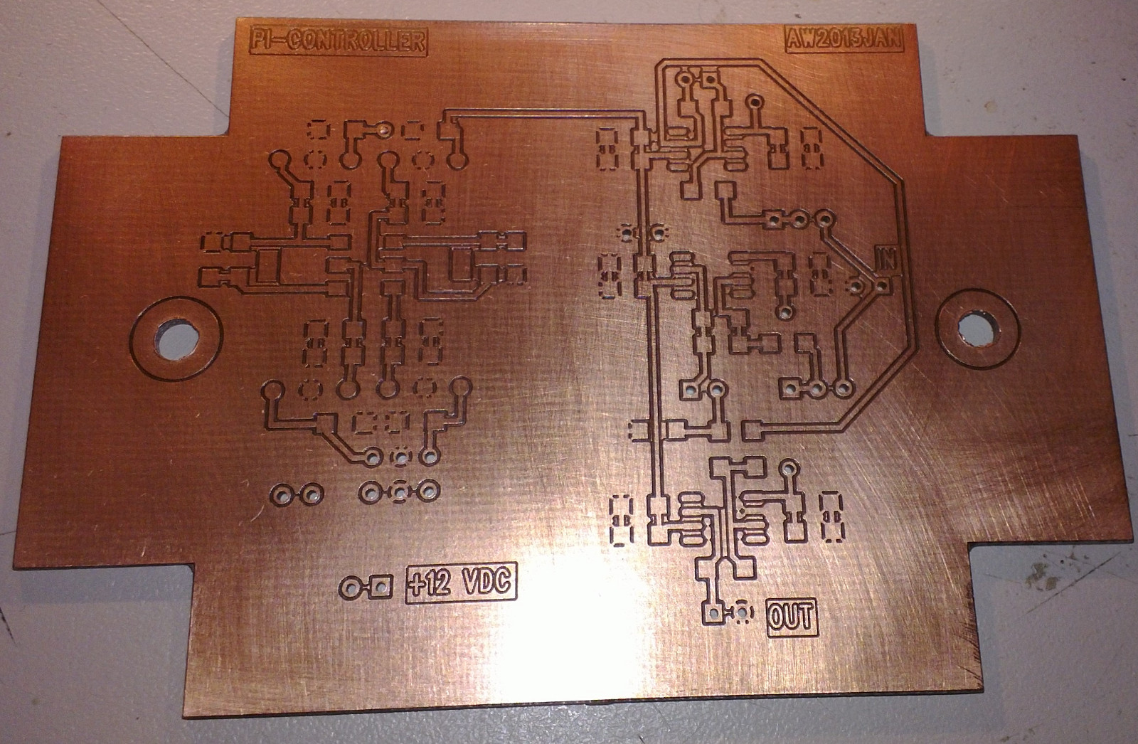
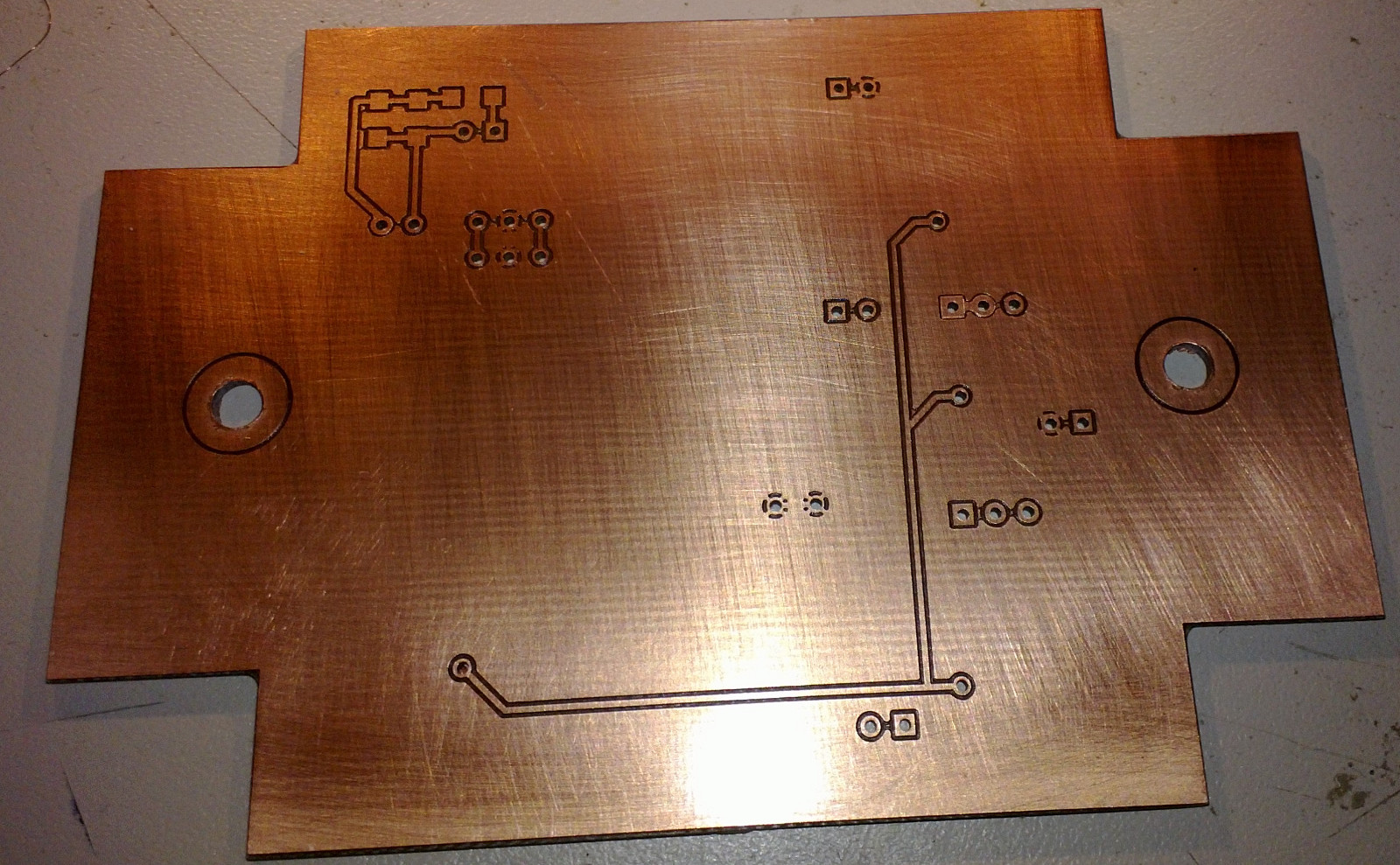
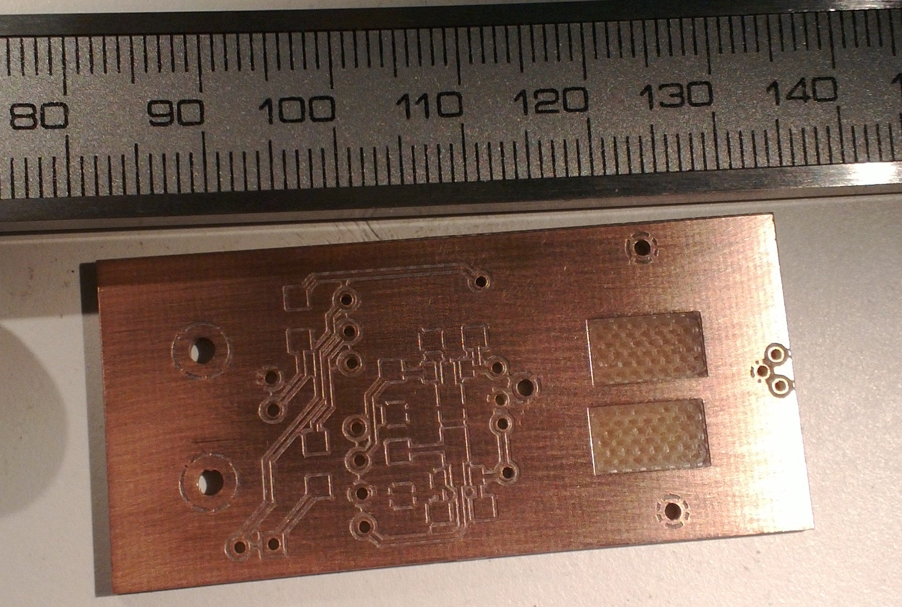
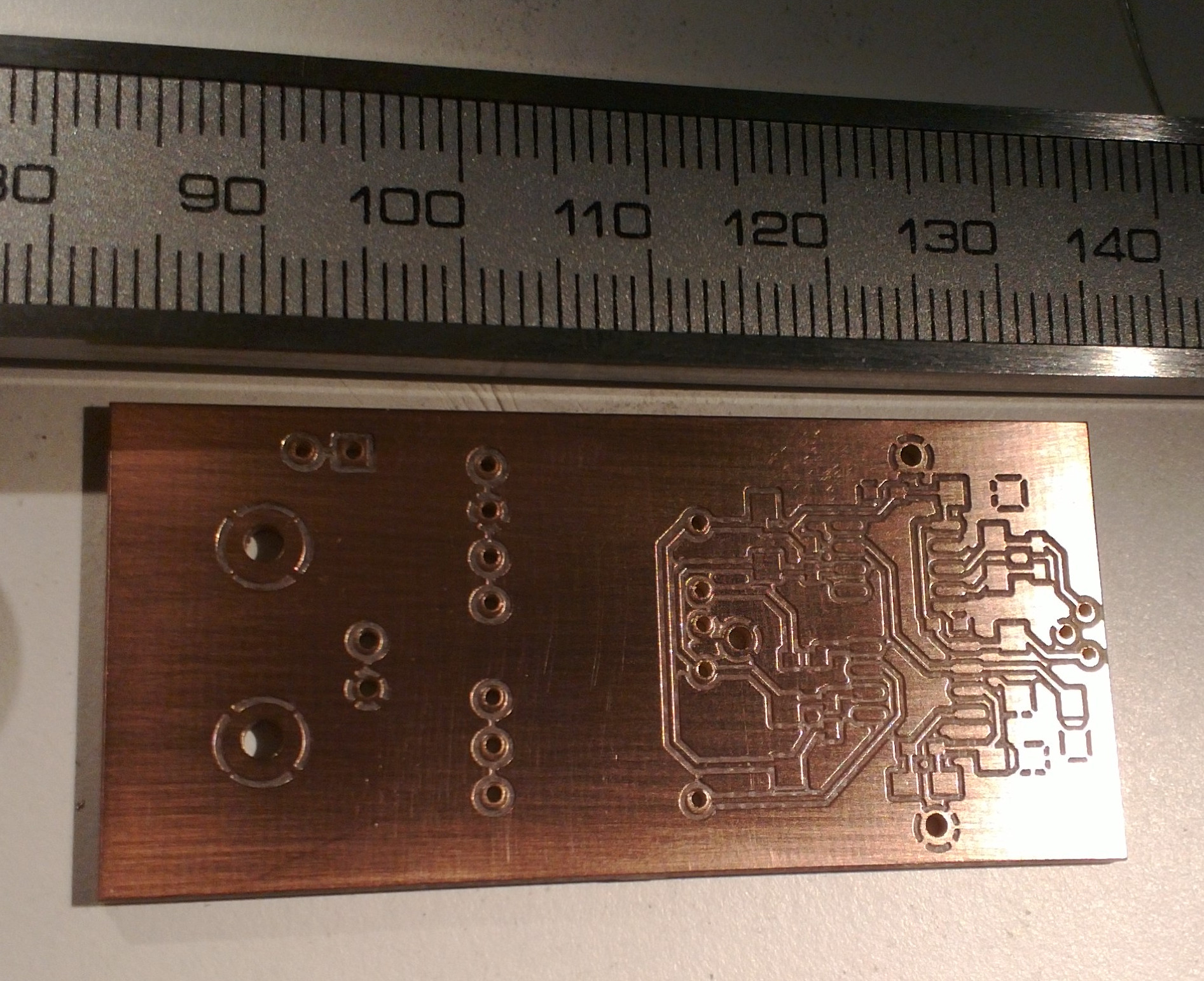
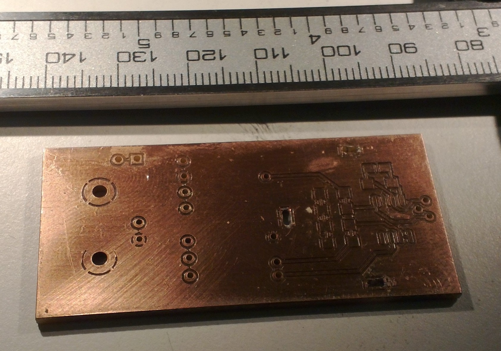
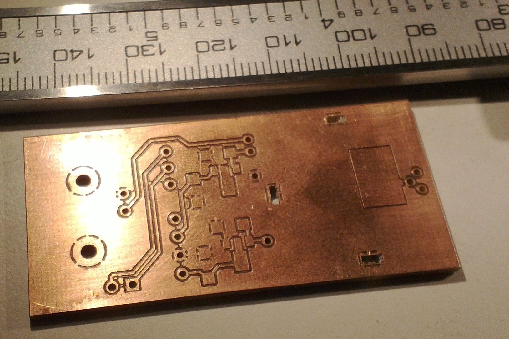
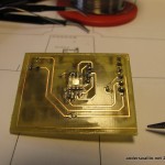
I made a first PCB using the original pcb-layout from the git repo, but the combination of a printer driver that produced a fuzzy mask and less than perfect etching skills didn't produce a satisfactory result. I then re-drew the GND copper-fill and some other traces on the PCB for bigger clearances and easier etching. Printed from adobe acrobat on windows the mask also has much better resolution than when printing from Document Viewer/Ubuntu.

Here are my modified masks in PDF format: hardware_etched_2011dec04 (note that the board outline is enlarged)

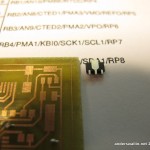
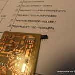
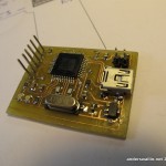
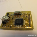
The PCB is clearly made for commercial production. There are vias under the microcontroller, which you can see from the pictures I have filed down after soldering so that the chip will fit on top. This isn't an issue with a commercially produced PCB where the vias are plated. Also, I noticed while starting to assemble the board that the large pad on the 3.3V regulator in the upper right corner will short out the trace drawn under it. Thus the silicone tape as insulation in the following picture. This is also not an issue with a commercial PCB since it will have an insulating soldermask.

Then on to programming. From the servodrive adventure I have an ICD2 programmer/debugger. However using it was challenging. I first tried 64-bit Windows 7. The latest Microchip MPLAB IDE does ship with 64-bit drivers, but they are hidden away in a special place, and require manual installation. No luck here, from device-manager/update-driver I couldn't get Win7 to recognize a valid driver using the instructions supplied.

I then tried 64-bit Ubuntu11.10. They have a Java version of MPLAB, called MPLAB X. It installs and runs nicely, but when I started digging in the documentation it turns out that product only supports the newer ICD3 programmer/debugger, not my older ICD2! (there might be ICD2 support in some old beta-version of MPLAB X, but I didn't search).

Oh well, it's nice we keep those old 32-bit Windows XP machines around in the lab! So I repeat for the third time the whole download and installation process on an old XP machine. That seems to work. The C-compiler which I vaguely remember being free previously now has a 60-day trial period after which Micrchip proudly proclaims it will stop producing nice binaries and start producing crap binaries. Strange. There's both a bootloader and a firmware project in the colorhug firmware repo. My guess is I only need to build and deploy the bootloader, and the firmware can be flashed from any machine after that. The bootloader requires a USB-library, which I didn't manage to find before I had to quit for the day... To be continued.

Note to self: future projects should use ATMEL or other microcontroller which (a) has a free/open-source toolchain for building the firmware, and (b) can be programmed directly over USB. The 6-pin ICSP connector is just big and ugly on a cute little board like this.

Another Nokia N9 vs. Garmin GPS test

These results are much like my previous ones. Close to buildings or other difficult places the N9 GPS performs significantly worse than the Garmin. This is somewhat surprising since the N900 performs very similar to a Garmin. Could better GPS-data on the N9 be just a software-update away? When is someone going to try to get TJ Lindfors's RTK-GPS Openmoko hack to work on the N9 ?!