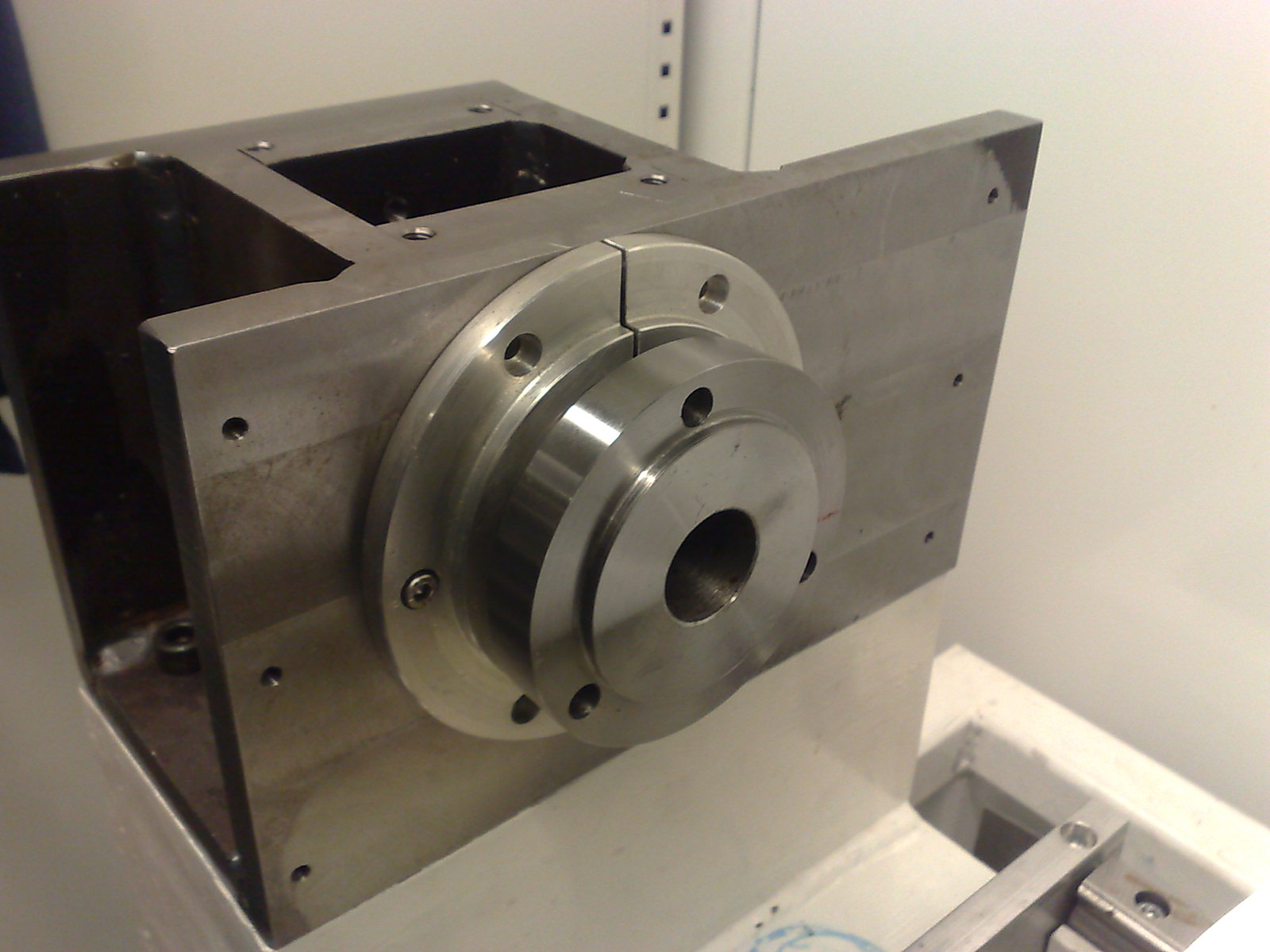
The lathe-project I bought in November is slowly moving forward. I got an Optimum/Quantum 100mm 3-jaw chuck for it today. Turns out the spindle needs to be disassembled to attach the chuck, so this was an opportunity to look at how the spindle is built.
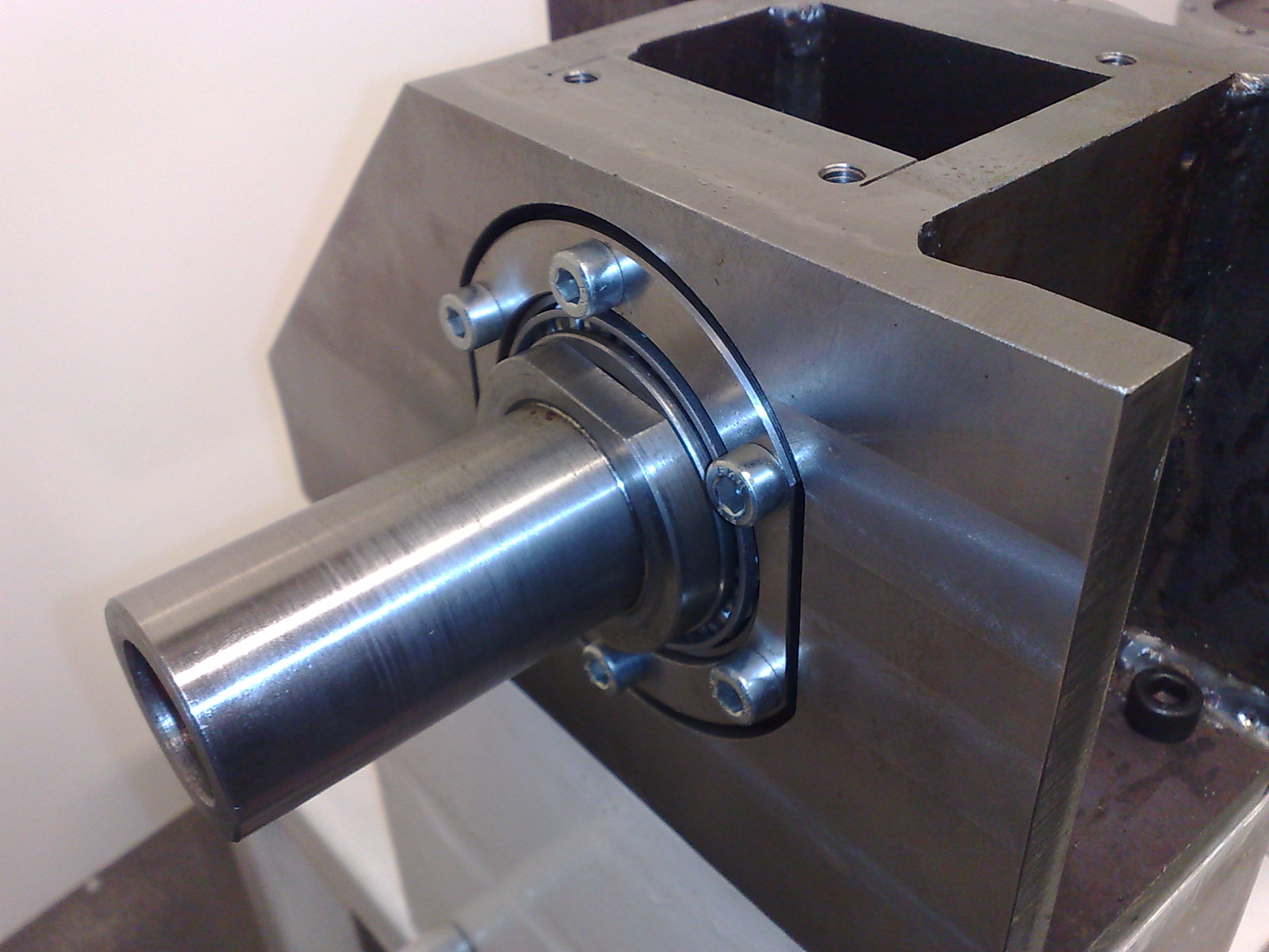
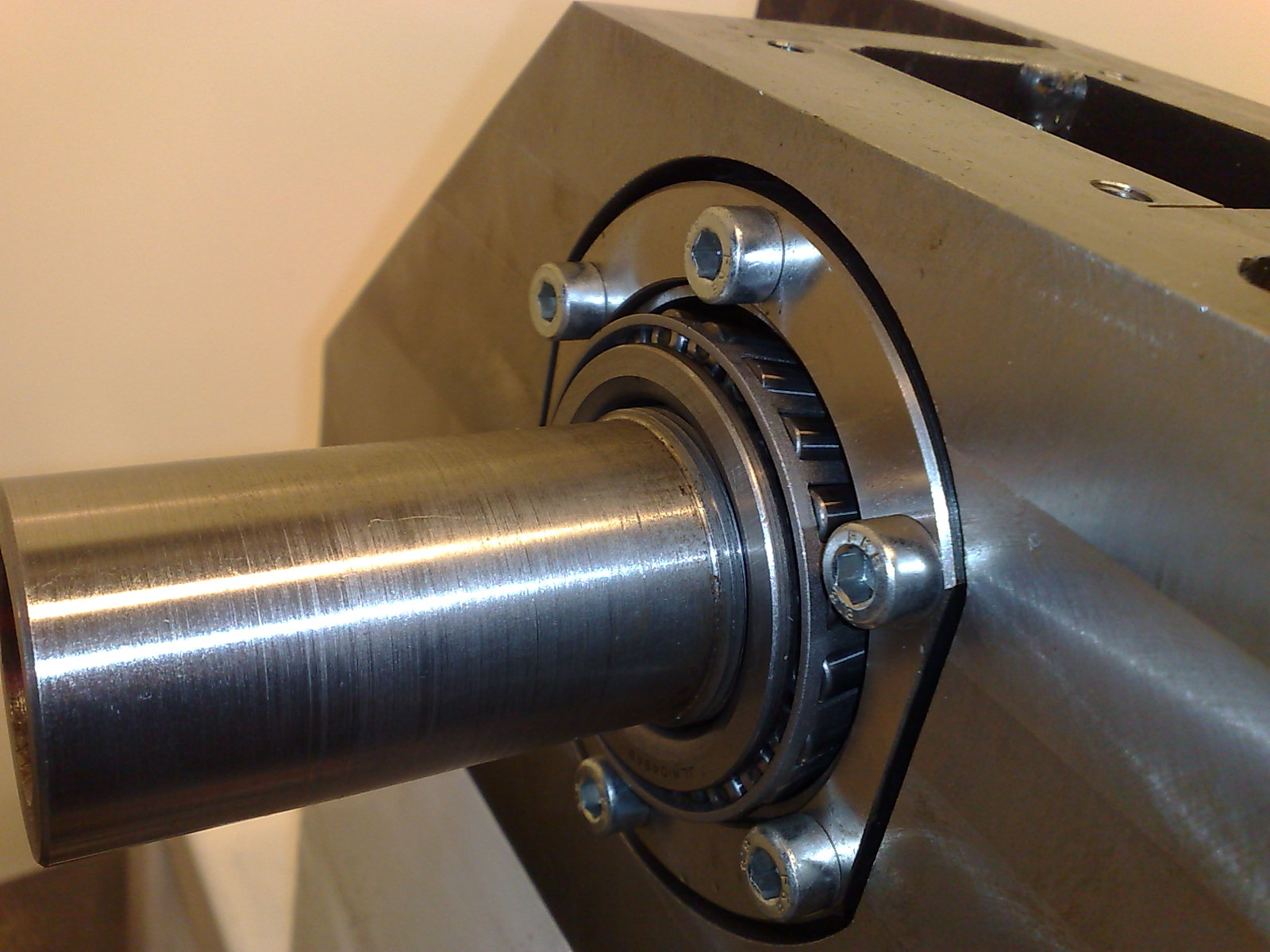
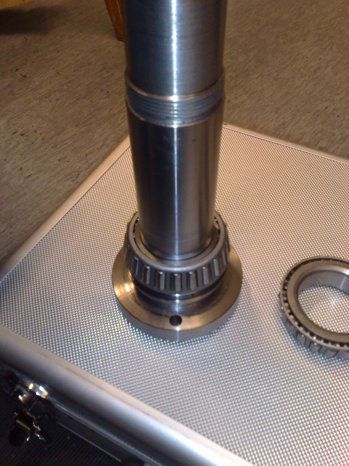
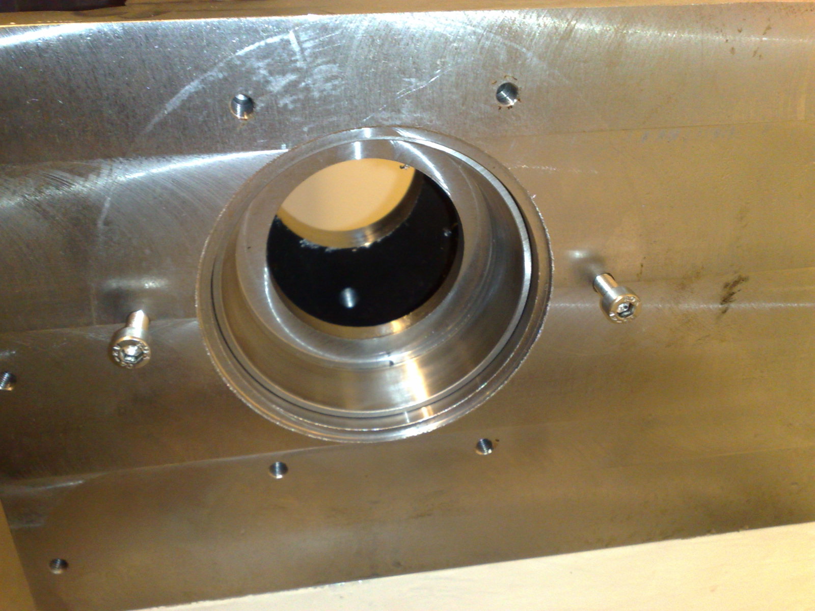
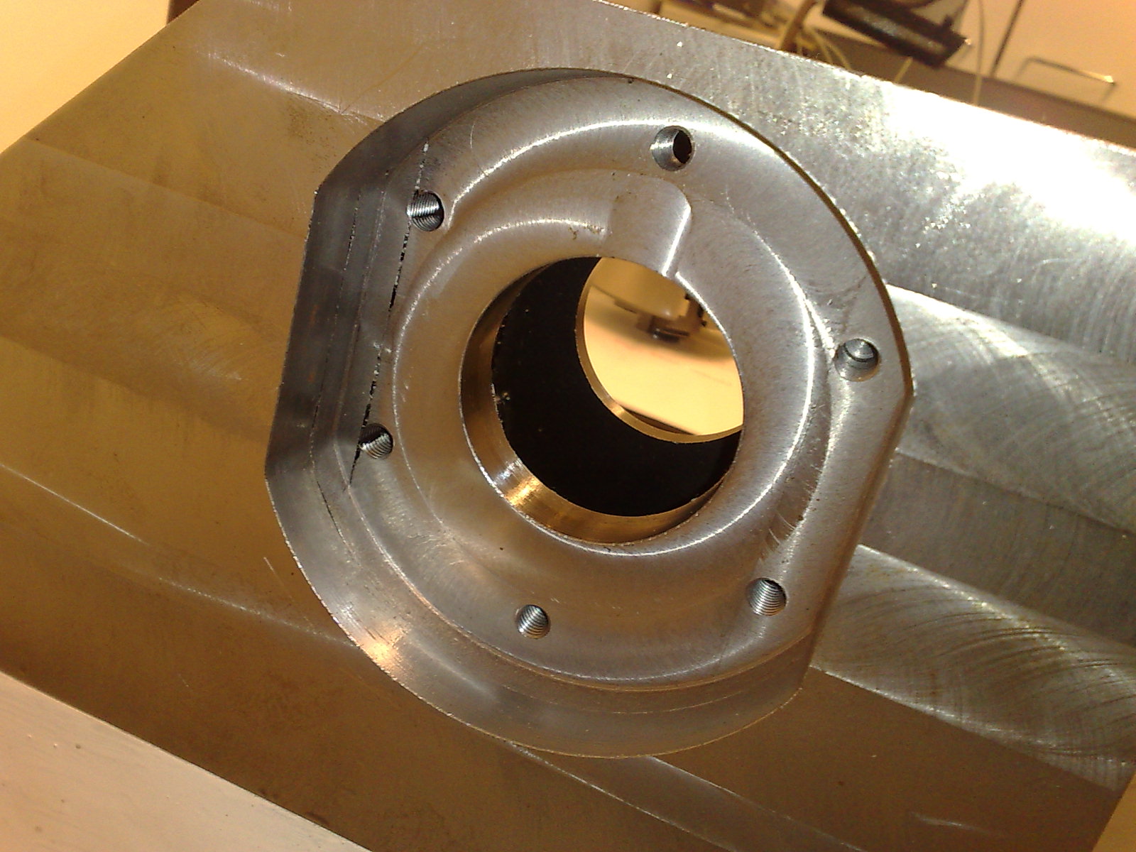
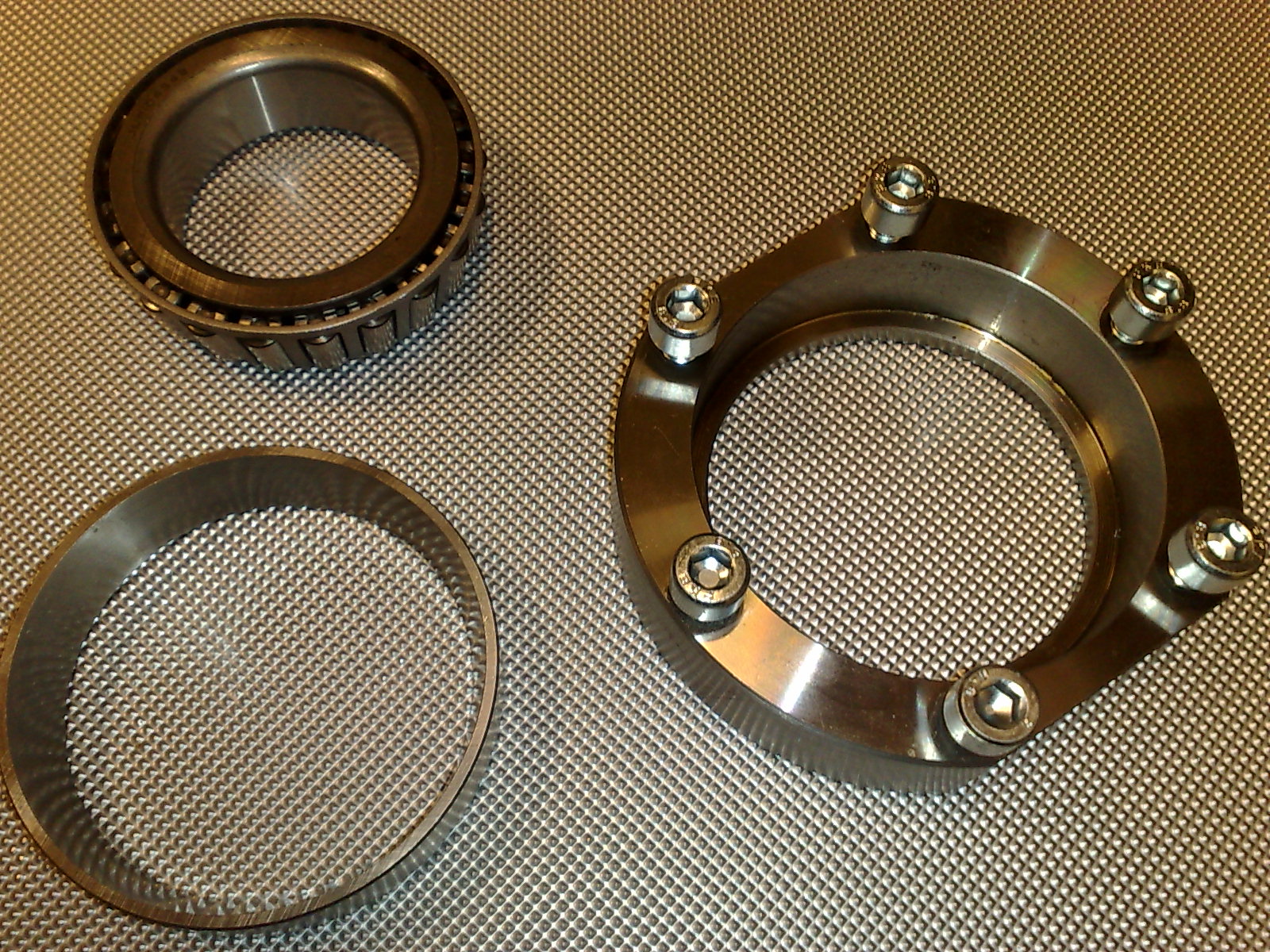
The front bearing seat is machined into the spindle box, while the back bearing seat is a separate bolted on part. The front bearing has a nice 2-part aluminium chip-guard which protects the bearing from coolant and chips. A chip/dust-guard for the back bearing would probably be a good idea too. The spindle is held in place with a nut against the back bearing that tightens the whole assembly. This nut will probably need a set-screw or something else to secure it rigidly (rapid accelerations, changes of direction etc. might otherwise loosen it?). The chuck attaches with three M8 hex bolts, and the 20mm ones which came with the chuck are a bit short - need to buy 3pcs 25mm M8 hex bolts. For now everything is dripping with anti-corrosion spray, but for use the bearings will require either grease or oil (oil is better for higher RPM?). Also, I need to source a timing-belt and 1:1 pulleys to transmit ca 2kW @ 3000-3500RPM from the spindle-servo up to the spindle. Any suggestions?