Monster torque servos

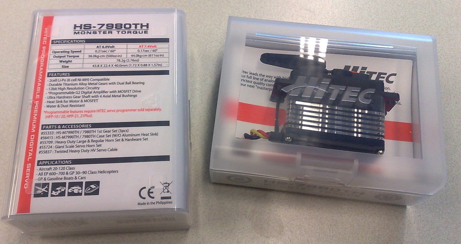
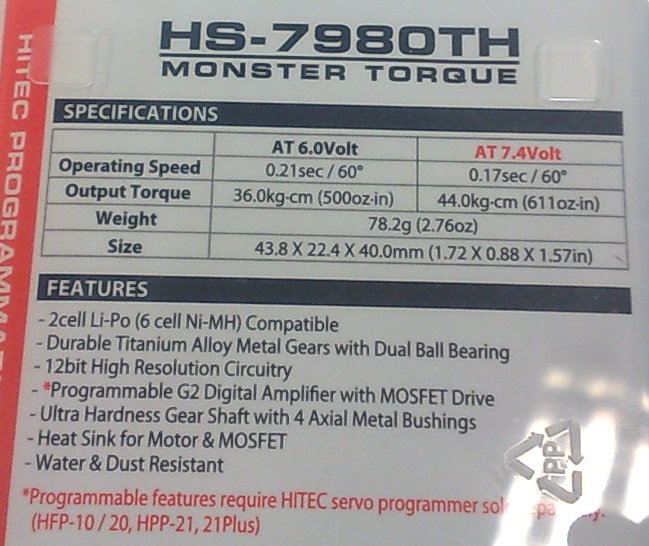
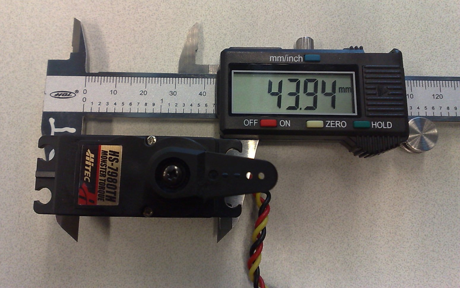
Gone is the HiTec light-blue box, and replaced with a clear one. These servos, which HiTec calls "monster torque" 🙂 are designed for either 6.0V or a LiPo pack at 7.4V. They are about 10% bigger than the standard 20x40 mm footprint, and produce 36 kg*cm (6.0V) or 44 kg*cm (7.4V) of torque. To be tried as a winch servo in the prototype PIKANTO.

Wires, wires, wires…

Number of wires from servo-motor to controller on my lathe build: 19.

1: Motor power U
2: Motor power V
3: Motor power W
4: Hall sensor +5V
5: Hall sensor U
6: Hall sensor V
7: Hall sensor W
8: Hall sensor GND
9: Encoder +5V
10: Encoder A
11: Encoder B
12: Encoder Z
13: Encoder GND
14: +Limit switch Common
15: +Limit switch N.O.
16: +Limit switch N.C.
17: -Limit/Home switch Common
18: -Limit/Home switch N.O.
19: -Limit/Home switch N.C.

wires

The motor currents go through the AMP-connecor, everything else through the 25-pin D-connector.

I'm glad the lathe only has two servos (and a spindle), I would go mad with a 5-axis machine...

Spindle servo encoder shaft

enoder_axle_before

The 1.75kW spindle-servo for the lathe only has resolver and hall-feedback. So I need to mount an incremental encoder with index pulse on it myself. The rotor for the hall-sensors attaches to the main motor shaft with an M6 bolt. Here I'm making my own M6 bolt with a long 'head'/shaft that will extend outside the back lid of the motor. I cheated a bit by starting with a 0.5" rod which already had an internal M6 thread. An M6 set-screw will form the bolt-part of the shaft, and is also used here to hold the part in the lathe. This was then turned down to ca 11mm to fit the hall-rotor, and 8mm for the part of the shaft that extends outside the motor and to which the encoder will mount.

Encoders are on order from digikey so they should arrive next week.

encoder_axle_after

By taking it slow and measuring a lot the 1949 Schaublin makes parts with tolerances approaching 0.01mm!

Spindle servo Hall-signals

motor_back resolver_and_hallsensors rotor hall_1 hall_2

Figured out the hall- and resolver-signals on the spindle servo today. There are two scope-pictures but the hall signal corresponding to the third phase is also OK, I just didn't save the screenshot. The pinout seems to be:

1: resolver a+
2: resolver a-
3: resolver b+
4: resolver b-
5: resolver c+
6: resolver c-
7: Hall A
8: Hall B
9: Hall C
10: +5V
11: GND
12: PE/case-ground

The Hall outputs require pull-up resistors, this test was with 1 kOhm resistors. If I install a normal A/B/Z encoder on the motor myself I should be able to drive it with a stock standard Brushless servodrive.

Lathe spindle servo

info art-nr power-connector brake back-open U_V_W enc-connector resolver

A closer look at the spindle-servo today. Googling for the model number does not immediately yield a datasheet, although I found a few similar-ish model numbers. The high-power connector is simple with U, V, W phases, Protective Earth, and +/- terminals for the solenoid brake. The brake opens at 24V and 0.67 A. The back can also be opened but doesn't reveal much more than an October 2001 manufacturing date. Hooking the scope to U, V, W and rotating the shaft with an electric drill produces some nice sine-waves. I'm not at all sure about the pinout of the encoder-connector, but looking at pairs 1/2, 3/4, and 5/6 seems to give something that could maybe be a resolver?