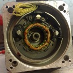
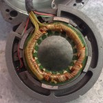
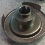
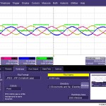
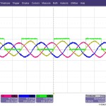
Figured out the hall- and resolver-signals on the spindle servo today. There are two scope-pictures but the hall signal corresponding to the third phase is also OK, I just didn't save the screenshot. The pinout seems to be:
1: resolver a+
2: resolver a-
3: resolver b+
4: resolver b-
5: resolver c+
6: resolver c-
7: Hall A
8: Hall B
9: Hall C
10: +5V
11: GND
12: PE/case-ground
The Hall outputs require pull-up resistors, this test was with 1 kOhm resistors. If I install a normal A/B/Z encoder on the motor myself I should be able to drive it with a stock standard Brushless servodrive.
