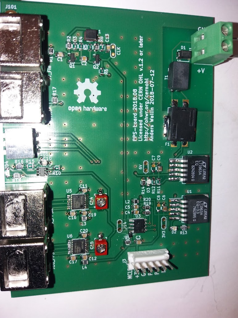
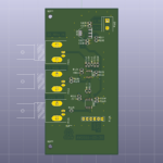
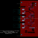
A second try at the PPS board, this time with the correct footprint for the transistors on the sine-to-square input stage.
Still some bugs left as I had to add a diode on the MCLR pin for the PIC-programmer to work correctly.
A second try at the PPS board, this time with the correct footprint for the transistors on the sine-to-square input stage.
Still some bugs left as I had to add a diode on the MCLR pin for the PIC-programmer to work correctly.
I put together a PICDIV frequency divider for use with a Rubidium clock.
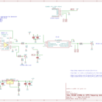
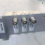
I used an LTC6957-3 to convert the 10 MHz sine-wave from the clock to a CMOS logic signal (square wave). The LTC6957-3 has two outputs, one is routed to a BNC connector output, the other is used as the clock for a PIC12F675. The PIC runs pd09.asm which outputs a 20 us long pulse every second - i.e. it divides the 10 MHz input frequency by 1e7. The PIC is programmed through a 5-pin 100 mil ICSP header.
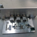
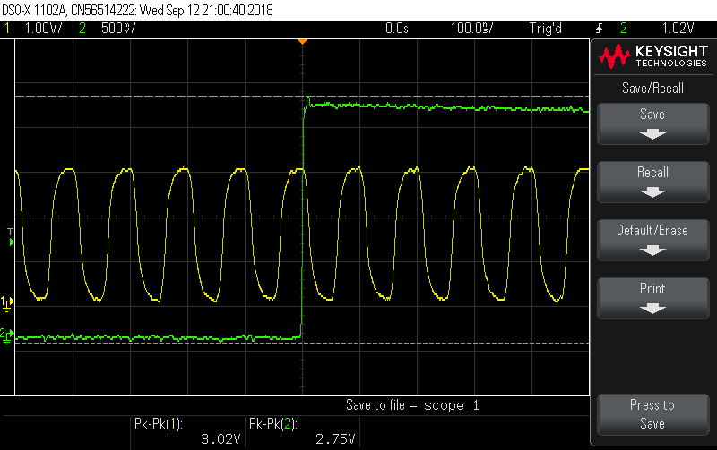
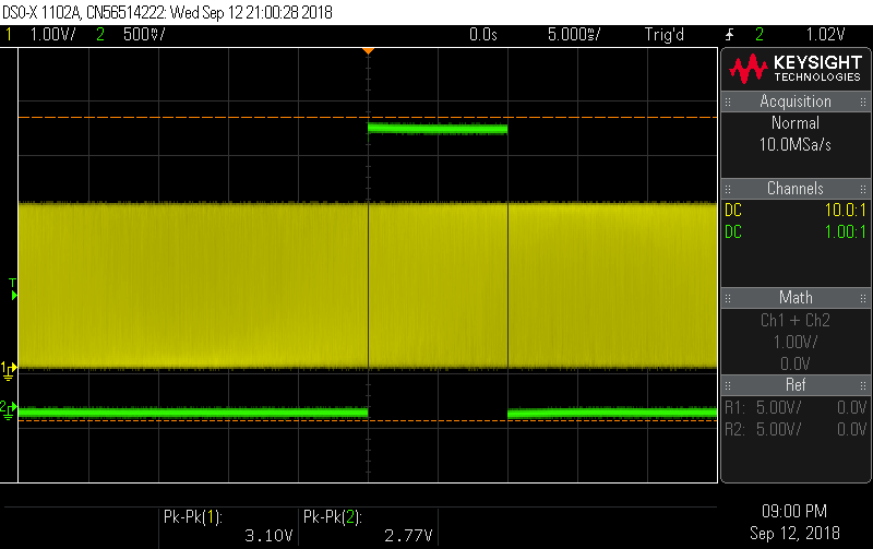
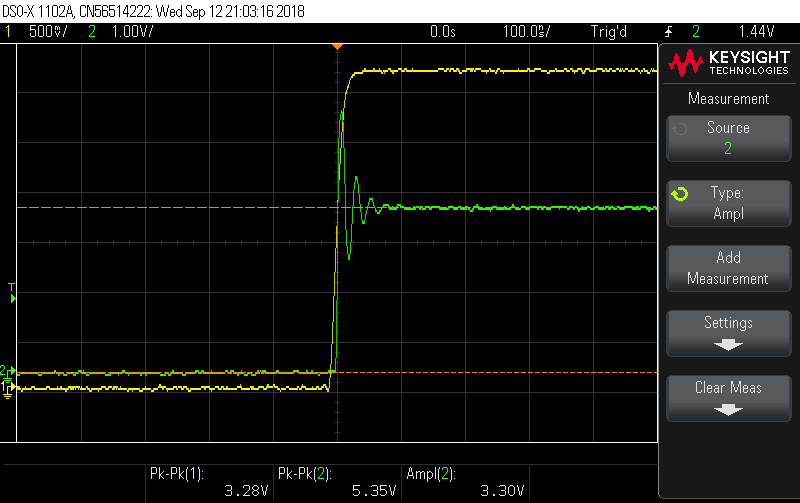
Here are some test-signals with a SRS PRS-10 as the source, and recorded on a Rigol scope.
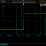
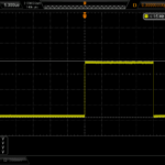
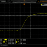
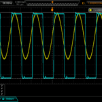
The outputs behave as expected, but the 1PPS from the PIC is only 700 mVpp into 50R - a bit low. When terminated to 1 MOhm the rise-time is much worse so this is best avoided. Perhaps a buffer or level-translator would be a good addition.
Finally phase-noise measurements on the 10 MHz CMOS output, performed with a 3120A phase-noise probe.
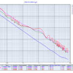
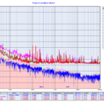
I tried shielding the circuit with aluminium foil and powering it from a +12 VDC lead-acid battery - however the three measurement runs look roughly similar. Perhaps the LM317 regulator is not a great choice here, and both the LTC sine-to-square chip and the PIC should have more bypass caps and decoupling (inductors, ferrites?). In any case the phase-noise is 10-20x better than the measurement noise from a typical counter (SR620 or 53230A), so any issues only show up with high-end phase-noise probes.
An order from RS delivered today with parts for a ColorHug, a device for color-calibrating your monitor.
The circuit is based on the TCS3200D color-sensor which RS had on their website when I made the order, but the delivery note lists the parts as "discontinued". So these have to be sourced from somewhere else.
