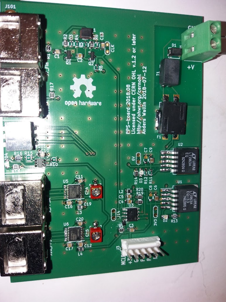
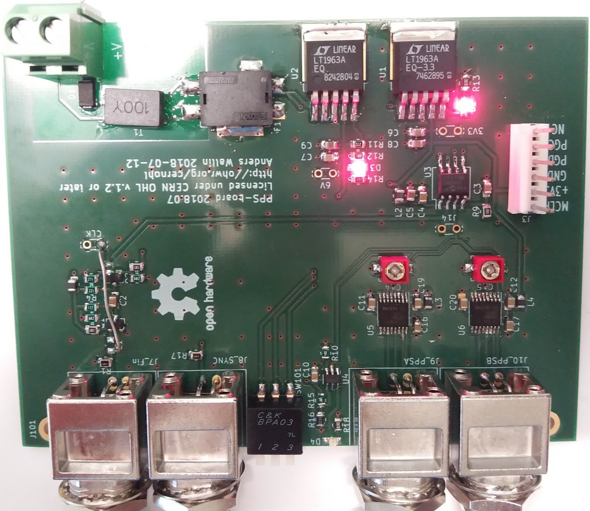
A second try at the PPS board, this time with the correct footprint for the transistors on the sine-to-square input stage.
Still some bugs left as I had to add a diode on the MCLR pin for the PIC-programmer to work correctly.
A second try at the PPS board, this time with the correct footprint for the transistors on the sine-to-square input stage.
Still some bugs left as I had to add a diode on the MCLR pin for the PIC-programmer to work correctly.
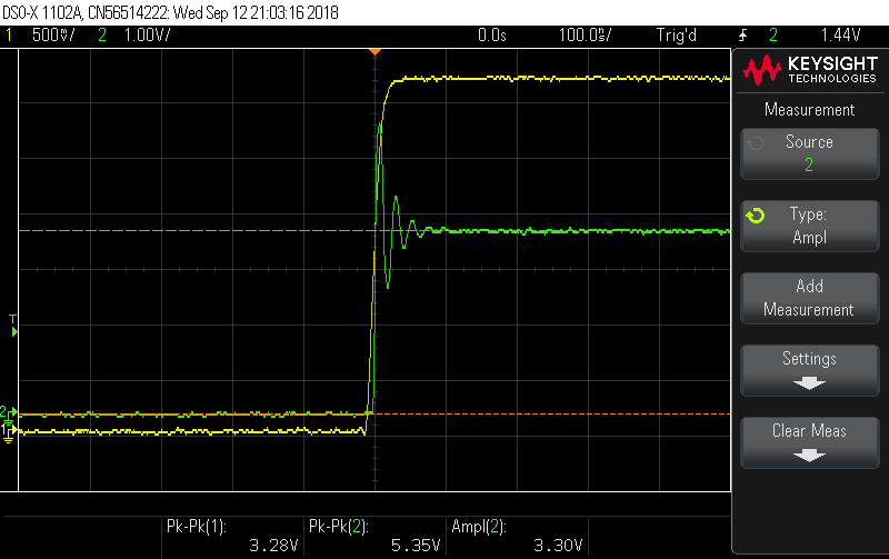
An evolution of my PICDIV-board from 2016. Takes 10MHz input and produces 1PPS (one pulse per second). This one has a TADD-2-mini inspired sine-to-square converter on the input (far left), a PIC12F675 with Tom van Baak's PICDIV-code (right), an ICSP-header for programming, and output-buffers inspired by the pulse distribution amplifier. A 3-position DIP-switch (middle left) allows config-changes, and a blinking LED indicates 1PPS (middle right).
Fixed a few bugs in the first PCB-revision and will order boards for version two soon. Eventually to be published on github/ohwr - stay tuned..
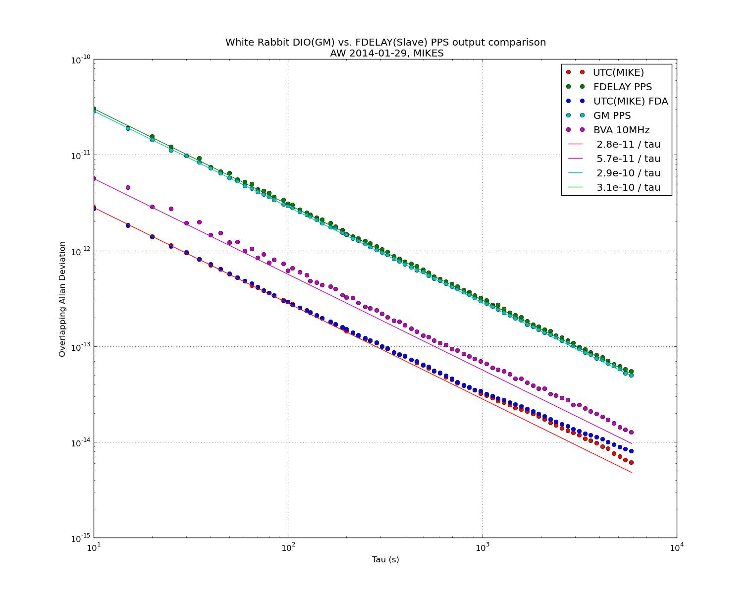
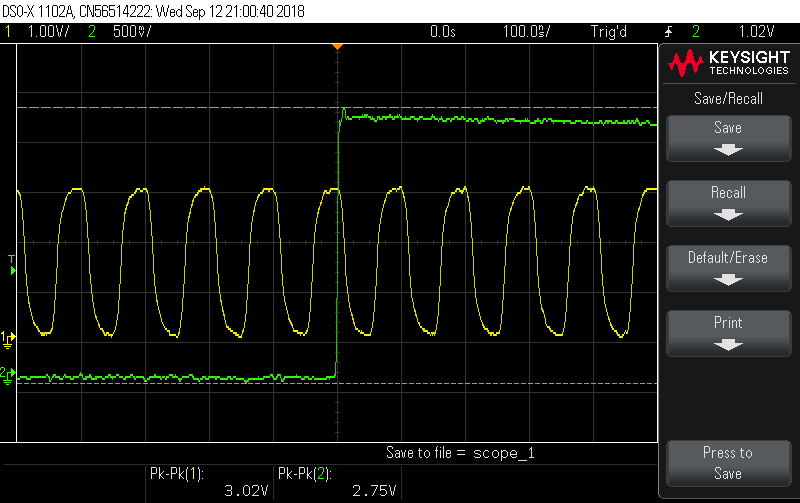
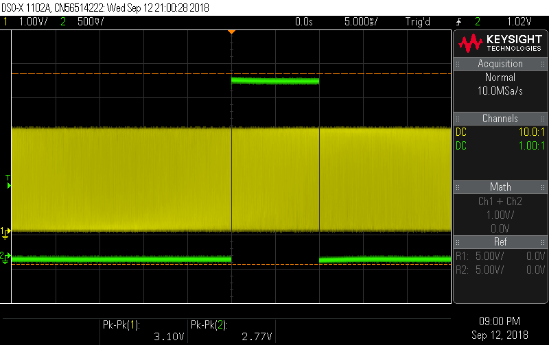
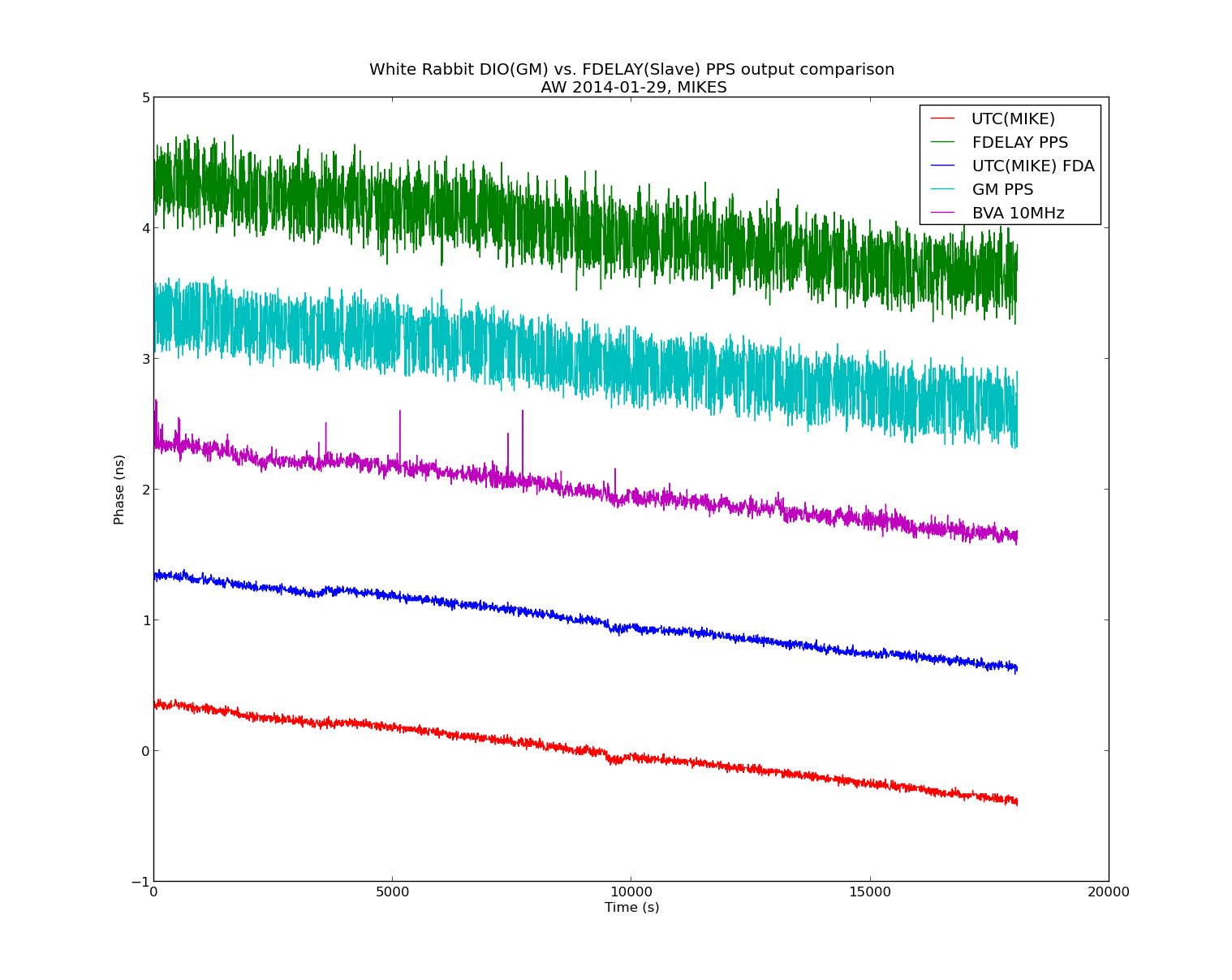
I ran a test to compare the quality of PPS outputs from a DIO (used as GM) and an FDELAY (used as slave) White Rabbit SPEC/FMC combinations. Here is the phase data measured with a Time-interval-counter. The nice clean traces are derived from a H-maser. We then lock a BVA (internally 2x multiplied to 10MHz) to this PPS signal. The GM node is locked to this 10MHz signal.
The average of each trace was removed, and the traces are offset for clarity.
The Allan deviations look like this. Both the DIO and FDELAY PPS outputs have allan deviations about 5x worse than the BVA used as input clock for the GM.