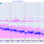
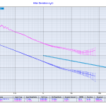
Update 2015-09-28: ADEV and Phase-noise measured with a 3120A:
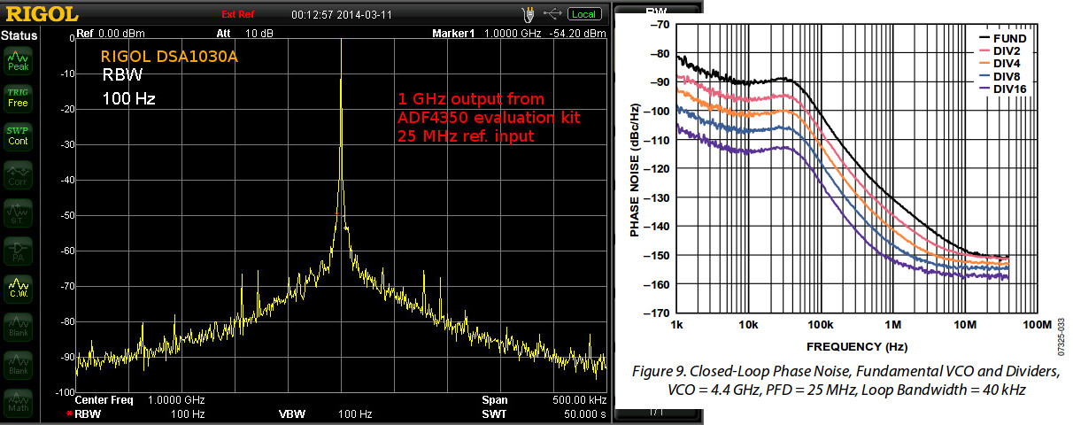
Here's the 1 GHz output of an ADF4350 PLL+VCO evaluation board, when used with a 25 MHz reference.
The datasheet shows a phase noise of around -100 dBc/Hz @ 1-100 kHz, so this measurement may in fact be dominated by the Rigol DSA1030A phase noise which is quoted as -88 dBc/Hz @ 10 kHz.
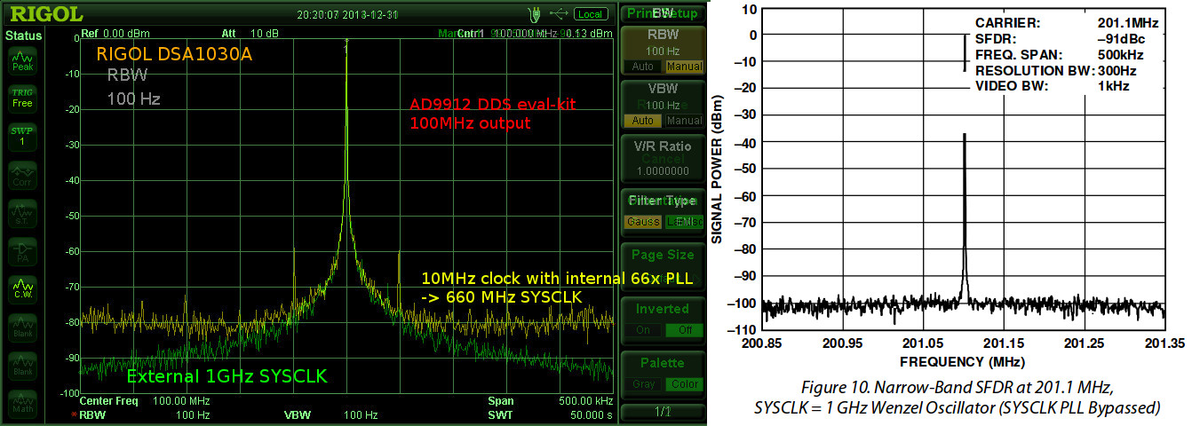
The 1 GHz output from the ADF4350 is used as a SYCLK input for an AD9912 DDS. The spectrum below shows a 100 MHz output signal from the DDS with either a 660 MHz or 1 GHz SYSCLK. The 660 MHz SYSCLK is from a 10 MHz reference multiplied 66x by the AD9912 on-board PLL. The 1 GHz SYSCLK is from the ADF4350, with the AD9912 PLL disabled.
The AD9912 output is clearly improved when using an external 1 GHz SYSCLK. The noise-floor drops from -80 dBm to below -90 dBm @ 250 kHz from the carrier. The spurious peaks at +/- 50 kHz disappear. However this result is still far from the datasheet result where all noise is below -95 dBm just a few kHz from the carrier. It shouldn't matter much that the datasheet shows a 200MHz output while I measured a 100 MHz output.
Again I suspect the Rigol DSA1030A's phase-noise performance of -88dBc/Hz @ 10 kHz may in fact significantly determine the shape of the peak. Maybe the real DDS output is a clean delta-peak, we just see it like this with the spectrum analyzer?
Martein/PA3AKE has similar but much nicer results over here: 1 GHz refclock and 14 MHz output from AD9910 DDS. Amazingly both these spectra show a noise-floor below -90 dBm @ 50 Hz! Maybe it's because the spectrum analyzer used (Wandel & Goltermann SNA-62) is much better?
Hi Anders,
I am trying to use the library you wrote for the AD9912. The problem is I want to use the native SPI instead of the bitbang SPI. Can you tell me which part of the library I need to change in order to utilize the speed of the native SPI.
Thanks
Wade
Hi Wade,
The AD9912 library calls SPIBitBang, a simple class that implements SPI over any three GPIO pins on the Arduino Due.
https://github.com/aewallin/Arduino-DDS/blob/master/ddscontrol/spibitbang.h
You could probably write an alternative SPI-class with the same interface as my SPIBitBang class - and use the AD9912 library with no changes.
If I read the arduino SPI reference correctly, then instead of shiftOut you would use SPI.transfer() for writing out bits over SPI.
I am not sure how you would implement reading bits from the AD9912 to the Arduino using native SPI. The reference documentation seems to assume there are separate MISO and MOSI pins, while the AD9912 uses a single pin for data transfer in both directions. I would think someone has already run into this and google might find an answer.
Anders
I think you can configure the AD9912 to work with either bidirectional data transfer or unidirectional. I think it is changeable from the initialization of the AD9912. Also can I just include spi.h instead of SPIBitBang.h, would this work?
Thanks
Wade
the standard SPI.h that comes with the Arduino libraries has a slightly different interface compared to my SPIBitBang.h.
you would need to rewrite all the SPI-functions so they use the built-in SPI.transfer() function.