Pulse distribution amplifier output skew

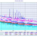
Here is the measured output delay skew from four of my "PDA 2017.01" designs, based on LT1711 comparator driving a 74AC14 schmidt trigger which in turn drives eight 74AC04 output-stages.

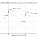
Also included is my earlier measurement of an Ettus OctoClock.

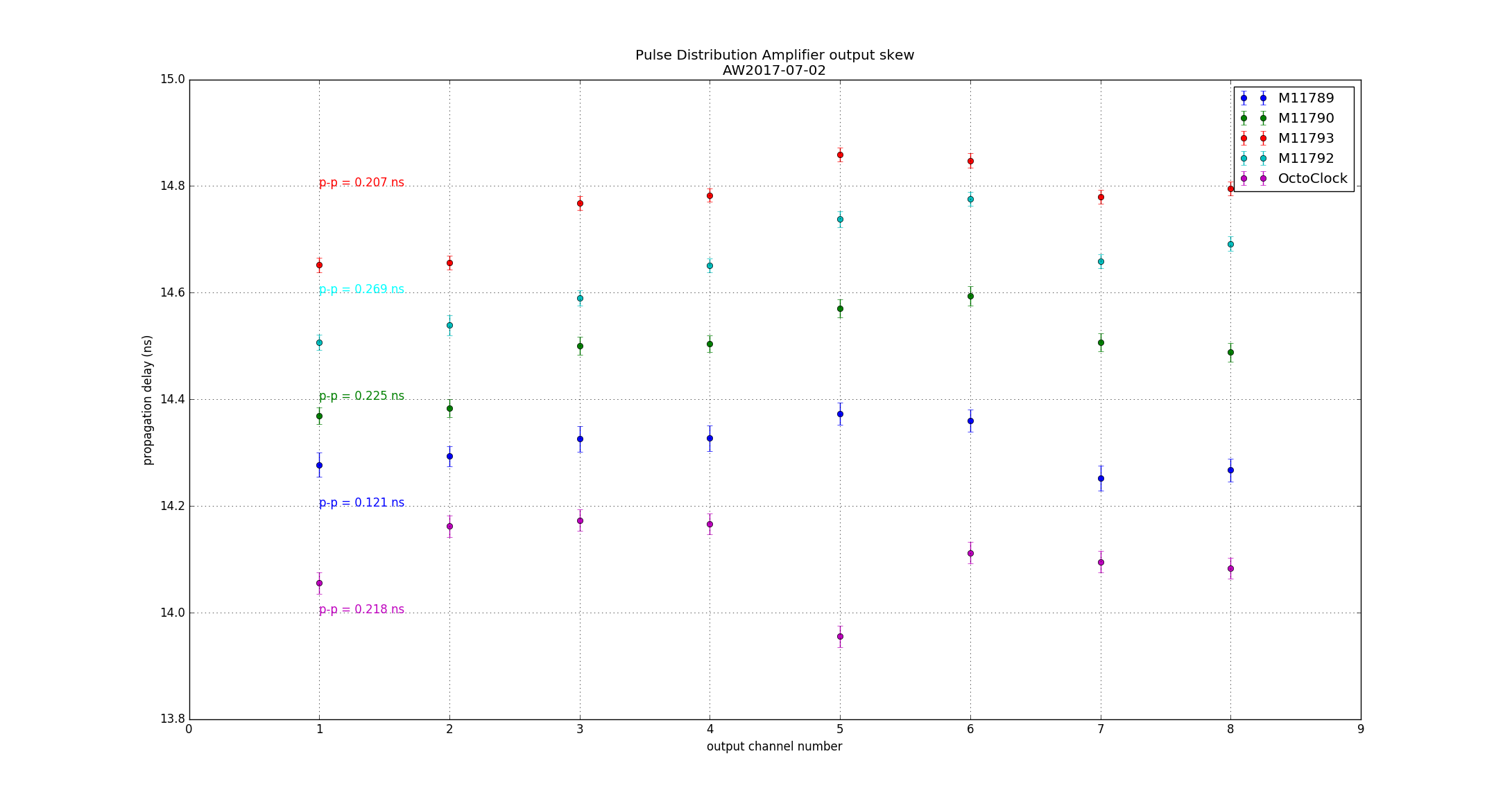
Although the PCB was designed with equal-length traces for the output stages it appears that channels 3-4 and 5-6 are consistently late, and some shortening of the traces would improve things. I tried this on one PCB (blue data points) with moderate success.

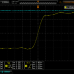
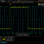
Measurement setup: 1PPS source to 50-ohm splitter. One output of the splitter drives CH1(start) of a time interval counter (HPAK 53230A), the other output drives the input of the pulse distribution amplifier. Outputs wired to CH2(stop) of the counter and measured for 100 s or more (delay is average of 100 pulses). Counter inputs DC-coupled, 50 Ohms, trigger level 1.0 V.

Ettus OctoClock distribution amplifier

I measured the phase-noise of an Ettus OctoClock distribution amplifier. These plots compare it to earlier measurements on an SRS FS710 and a Symmetricom 6502 as well as my own TADD-1 inspired AD8055 prototype.

OctoClock schematic here: http://files.ettus.com/schematics/octoclock/octoclock.pdf

10 MHz clock-distribution chip: http://www.ti.com/lit/ds/symlink/cdce18005.pdf

For time-nuts kind of stuff (H-masers!) the 10 MHz phase-noise doesn't look that great, and there is something funky going on in the AM noise!? The box is powered by a +6 VDC wall-wart PSU which is probably the cause of all those spikes...

The PPS-channels are based on 7404 hex-inverters and look OK. 200ps of skew is equivalent to 4 cm of trace-length (?) - which seems like a lot if there was an effort to minimize it... For a 1 V/ns rise-time pulse 200ps is equivalent to 200mV of DC-offset in either the signal or the counter trigger-level which also seems like a lot?