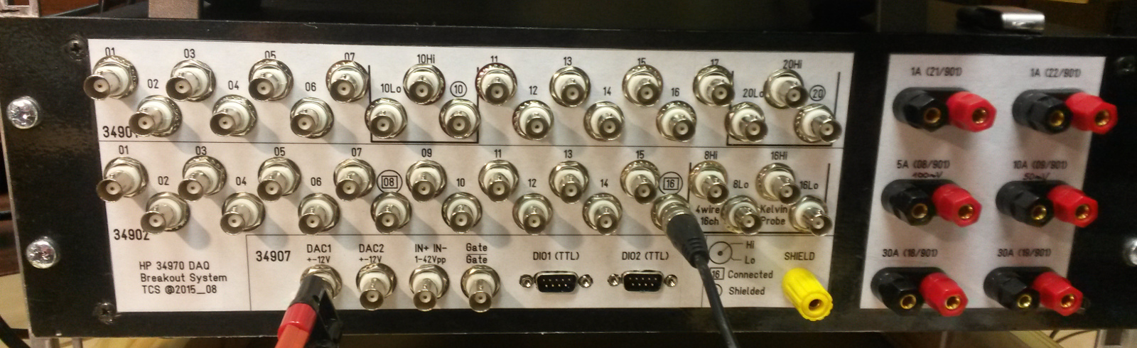
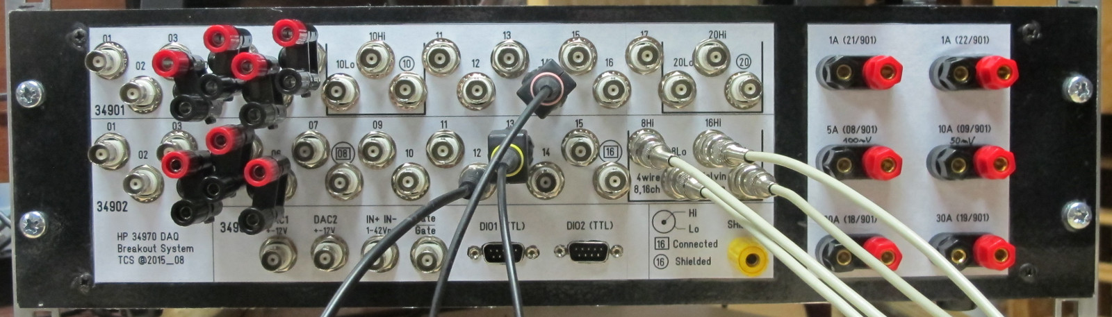
Update 2015-09-16: Csaba Toth sent a picture of his front-panel for these breakout boards. Very nice finish with text/graphics on the 19" rack panel!
Update 2015-05-15: Files for PCB manufacturing: top, bottom, outline Gerber files, and Excellon drill files.
When opened with e.g. gerberview they should look like this:
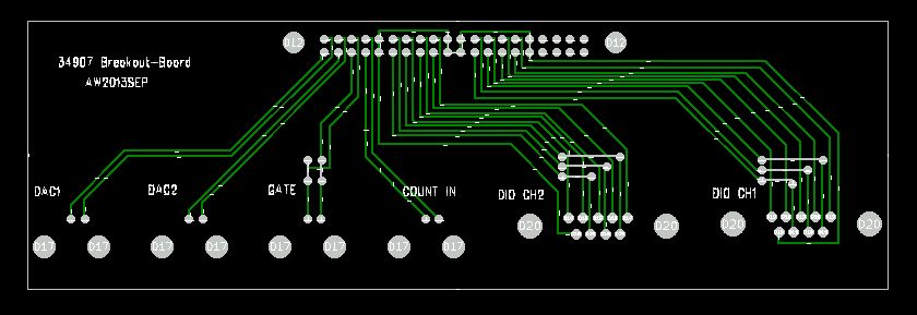
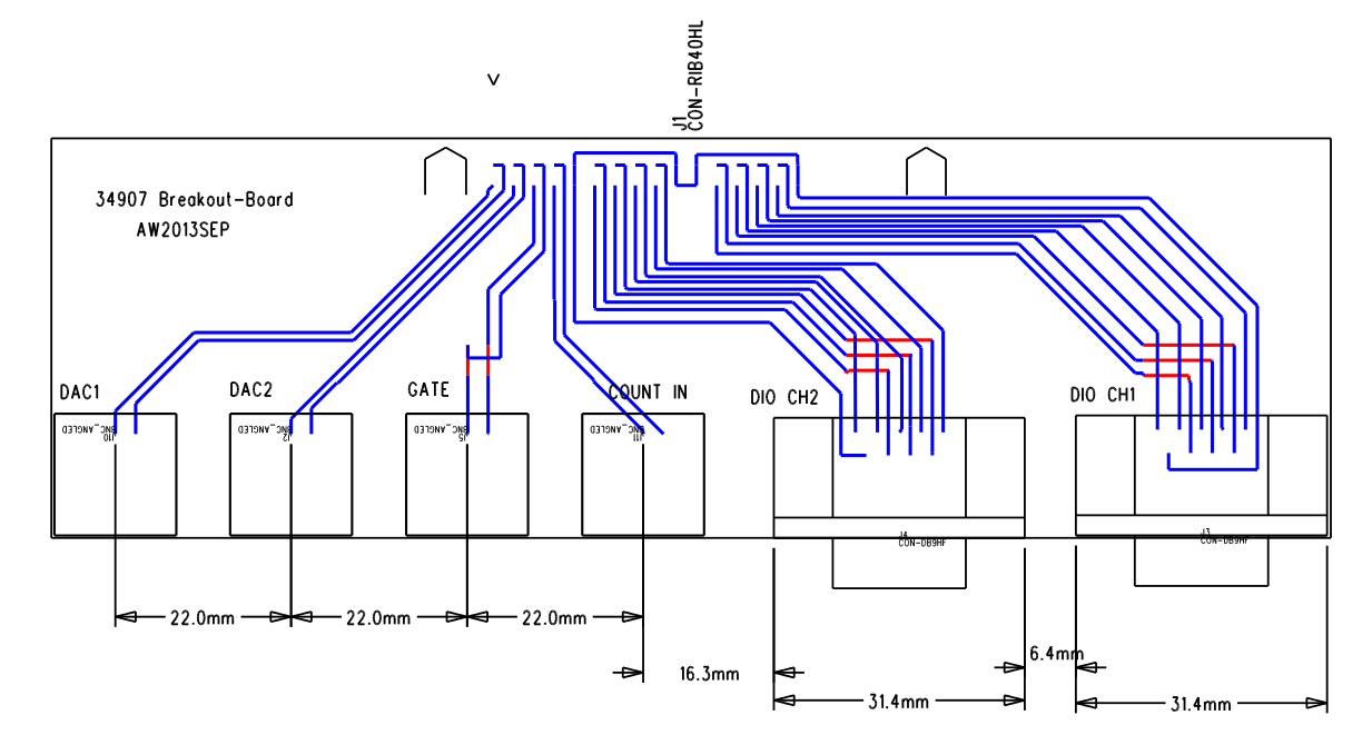
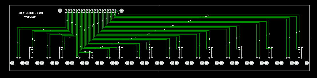 The connector placement is shown here (sorry I don't have a drawing for the one with 20 BNC connectors):
A frustratingly large portion of any electronics or control system build has to do with cables and connectors. So here we go...
I'm using an Agilent 34970A datalogger/switch, which is a 6.5 digit (~22 bit) multimeter that takes up to three plug-in modules with various functions.
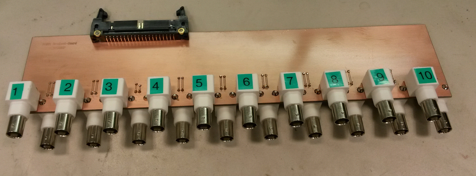
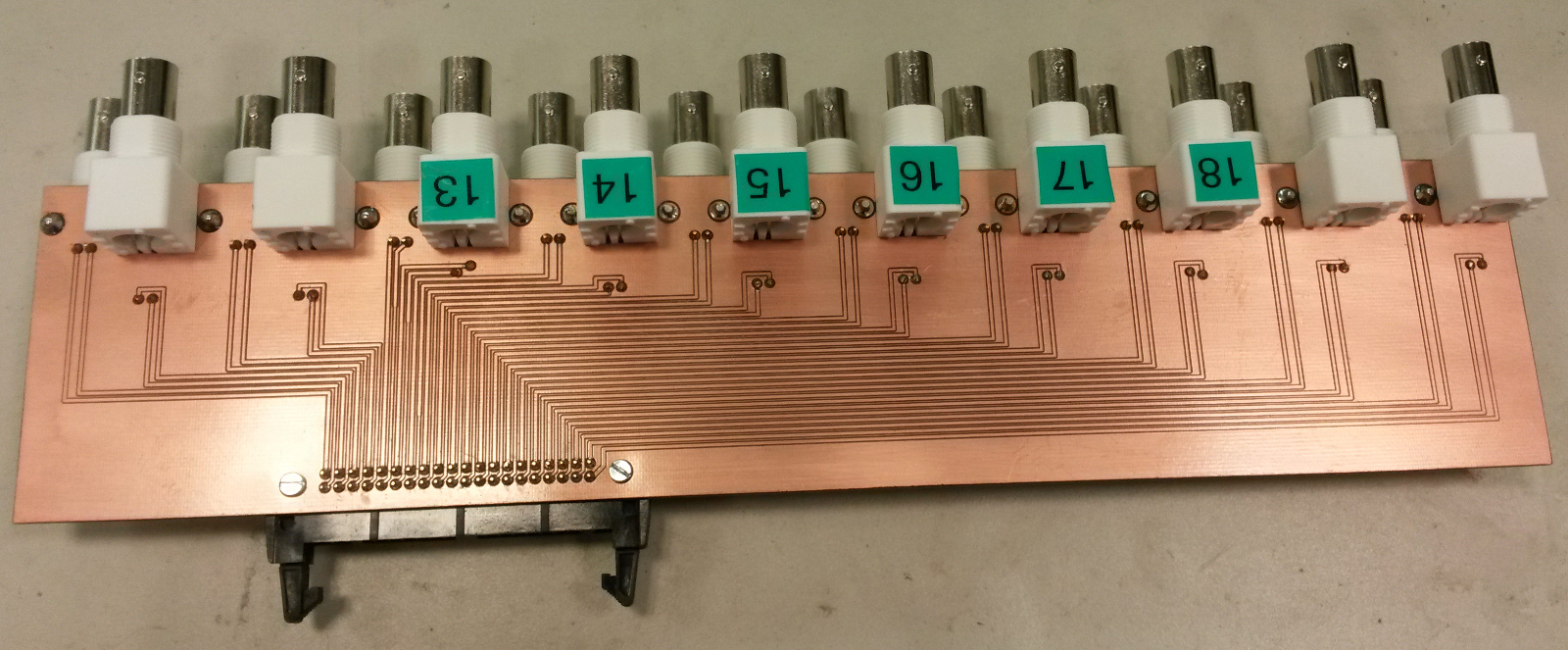
I'm using one 34901A module for 20 channels of DC voltage inputs. On the module there are 40 screw-terminals for these voltages which I have connected to a 40-pin ribbon cable that connects to this breakout board with 20 BNC connectors. Our PCB-mill can do 300mm long PCBs, which is just long enough for this board if the BNC connectors are interleaved on different sides of the board. Mounting BNC-connectors right next to each other on the same side is bad idea anyway as the connectors on the cables will not fit that closely. It should be possible to mount the whole thing in a 1U 19" rack panel.
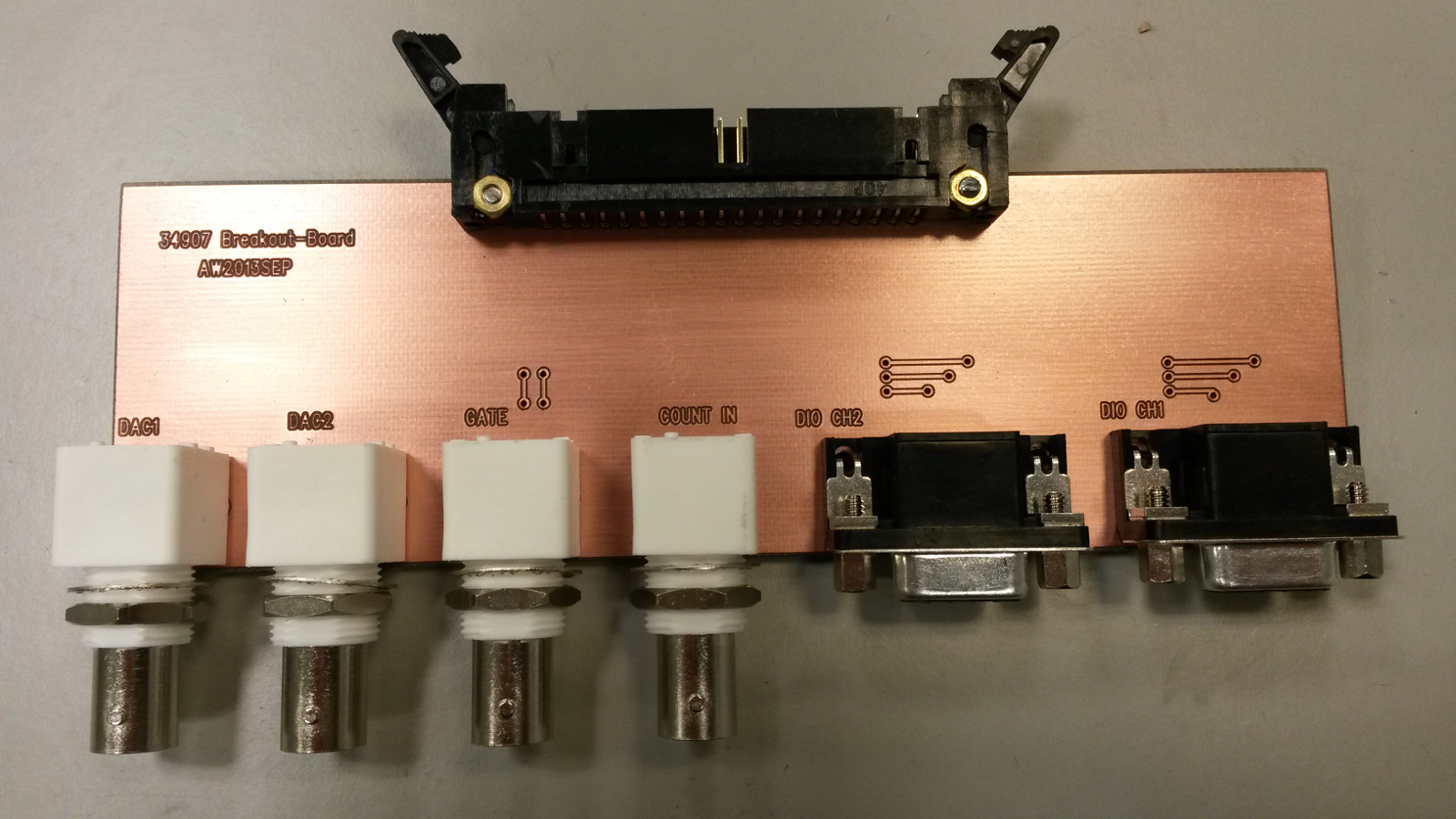
For controlling the TEC drive I need analog outputs, provided by a 34907A module. Again I'm using a 40-pin ribbon cable from the screw-terminals on the module, and the breakout board has four BNC connectors: Two DAC outputs, one counter input, and a gate input for the counter). Additionally there are two 8-bit digital I/O ports which are routed to two DB9 connectors on the breakout board.