Faster waterlines with OpenMP

This example has three times more fibers, and thus also CL-points, than the original one, but it still runs in a reasonable time of ~15s because (1) I hard-coded the matrix-determinant expressions everywhere instead of relying on a slow general purpose function and (2) the batch-processing of the fibers now uses OpenMP in order to put all those multi-cores to work.

(red=vertex contacts, green=facet contacts, blue=edge contacts)

My initial point-ordering scheme based on a complete breadth-first-search at each CL-point is a bit naive and slow (that's not included in the 15s time), so that still needs more work.

Waterline toolpaths, part 3

I've written a function that looks at the weave and produces a boost adjacency-list graph of it. The graph can then be split up into separate disconnected components using connected_components. To illustrate this, the second highest waterline in the picture below has six disconnected components: around the beak, belly, and toes(4).  When we know we are dealing with one connected component we pick a starting point at random. I'm then using breadth_first_search from this starting point to find the distance, along the graph, from this starting CL-point to all other CL-points. We choose the point with the minimum distance (along the graph) as the next point. Sometimes many points have the same distance from the source vertex and another way of choosing between them is required (I'm now picking the one which is closest in 2D distance to the source, but this may not be correct). We then mark the newly found CL-point "done", and proceed with another breadth_first_search with this vertex as the source. That means that the graph-search runs N times if we have N CL-points, which is not very efficient...

So, compared to previously, we now have for each waterline a list-of-lists where each sub-list is a loop, or an ordered list of CL-points. The yellow lines connect adjacent CL-points.

waterline_tux

There's still a donut-case, where one connected component of the weave produces more than one loop, which the code doesn't handle correctly.

Waterline toolpaths, part 2

demo_waterlines

After the proof-of-principle waterline experiments two days ago I've modified the KD-tree search so that triangles overlapping with the cutter can be searched for in the XZ and YZ planes (in addition to the XY-plane, which was needed for drop-cutter). This dramatically reduces the number of triangles which go through the pushCutter function and makes it possible to run some tests on small to medium STL files.

Currently all the CL-points come out of the algorithm in an undefined almost random order. I'm just plotting them all and they are closely spaced, so it looks like a path, but the algorithm has no idea in which order the CL-points should be visited. Before these waterlines are of any use a second algorithm is required which inspects the weave and (a) comes up with the number of "loops" or "rings" (what should we name these?) at each waterline and (b) sorts the CL-points in each loop into the right order. The upstream user of these waterline loops can then decide in which order to visit the waterlines at each z-height, and within one waterline in which order to visit the loops. Any CL-point in a loop is as good as any other, so the upstream user can also choose where to start/stop the toolpath around the loop.

My idea for this is to turn the weave in to a graph and use the Boost Graph Library which has a function for returning the number of connected components (part (a) above), and then perhaps the All-pairs shortest path algorithm to find adjacent CL-points (part (b) above). Any other ideas?

Here's the obligatory Tux example, where it took 96 seconds to generate five waterlines.

tux_waterlines

Waterline toolpath experiment

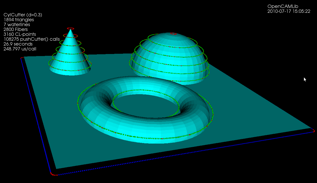
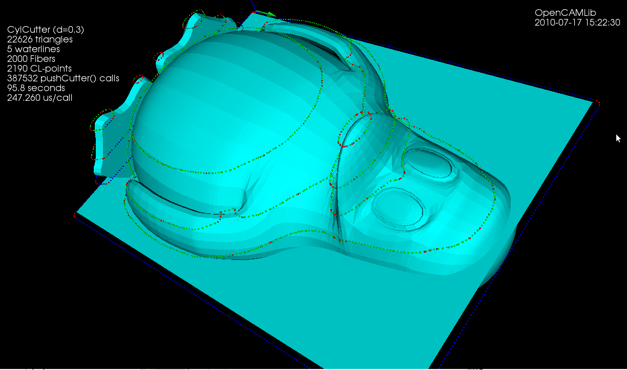
The logical next step from drop-cutter ("axial tool projection" or "z-projection machining") is to instead push the cutter sideways("radial tool projection") against the model and get waterline (or "z-slice") paths. In addition to waterline finish-paths these paths can be used in roughing where they define pockets for 2D machining/clearing of stock. The general purpose tool-location function would be a non-axial tool projection, but I'm not going there unless someone sends me a state of the art 5-axis VMC as a present!

Push-cutter is different from drop-cutter, because in drop-cutter for 3-axis machining there is always only one right answer. There's one z-height where the cutter is positioned as low as possible, but doesn't interfere with the model. In drop-cutter positioning the tool above this z-height is OK, but dropping it further down is an illegal move which causes overcutting.

In push-cutter we push the cutter along a line (called a "fiber") in the xy-plane, and search for CL-points where the cutter touches a triangle, together with illegal points or stretches/intervals along the fiber where the cutter interferes. There are going to be many of these points and intervals, so the fiber needs to keep track of everything using a list of interfering intervals (the endpoints of the intervals are valid CL-points).
Similarly to drop-cutter, where a path is sampled along points in the (x, y) plane, we now need to build up our waterline-path by inserting closely spaced fibers in the x-direction and the y-direction. Eventually the CL-points start to form a continuous waterline, if we hook up the points into a list in the correct order. The x- and y-fibers form a grid (or mesh/weave), a kind of graph, which can be used to figure out the correct ordering of the CL-points (not implemented yet, see BGL).

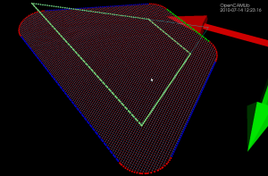
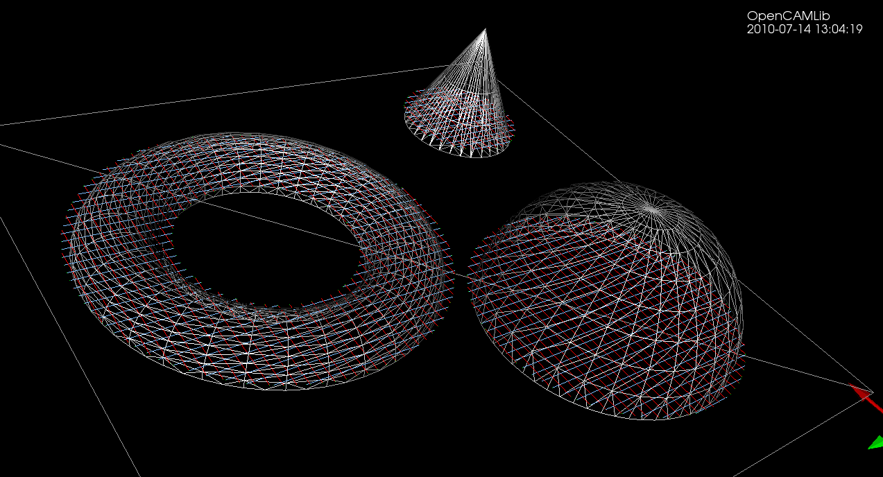
This picture shows the original triangle (thin cyan lines), X-fibers (red lines), Y-fibers (blue lines), and the endpoints of the fibers, which are CL-points (colored by which element of the triangle they are hitting: red=vertex, green=facet, blue=edge). The light-green points are CC-points, i.e. points where the cutter makes contact with the triangle. This initial experiment uses a cylindrical cutter, and I expect the spherical cutter to follow soon, while the toroid will be more difficult...
weave

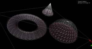
This picture does not show the fibers/weave, only CL-points, calculated at many different z-heights.
waterline_experiment

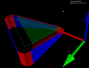
If the low-level functions are written right these ideas extend easily from the one-triangle test and debugging case to the practically more important and interesting many-triangle case: (note how now the weave-graph has three disconnected components)

demo_stl_waterline

Coming to an open-source CAM-system near you this summer/fall...