Drop-cutter again

This is about my third rewrite of this fairly simple cam-algorithm where the cutter is dropped from above until it touches a triangle. It's now in C++ with Boost-python bindings and with visualization using vtk.

The cutter-location points are calculated by bringing the cutter into contact with the vertices of the triangle (green cl-points), the edges (red cl-points), and the facet (blue cl-points). Then the cl-point with the highest Z-value is selected as the final cutter location. At the white points we did not make contact with the triangle at all.

If you look closely enough, all surfaces in the world are made of triangles, even Tux:

Due to compression, the video might not show enough detail, so here's a screenshot:

frame059

I wonder if anyone is still interested in this stuff? Given enough time I would like to develop waterline-paths and an octree-based cutting simulator also. It would help if these algorithms were incorporated in a CAD-program, or someone would develop a GUI.

Drop-Cutter in C# - v2

I think I've found the problems with my C# drop-cutter algorithm. The first bug was a trivial one where in the edge-test the rotation of the segment-under-test was messed up. The second one was not the facet-test itself but incorrect surface normal data. There's something going on that makes pre-calculated surface normal data not 'stick' correctly to the triangle object for later use. So here I'm re-calculating the normal data again just before the facet test.

The next step is to speed up things with a smarter kd-tree based search for which triangles are under the cutter. I've added bounding-boxes to the Cutter and Triangle classes. Running the above example the DropCutter function is called a total of 4735000 times, and of those only less than 5%, or 236539 to be exact, are useful calls, i.e. the triangle bounding box intersects the cutter bounding box, which means there's a chance that we are contacting the cutter against the triangle. The idea with the kd-tree then is to pre-search for triangles under the cutter to make less of those (supposedly expensive) redundant calls to DropCutter.

On my T5600 processor machine the above example runs in about 5 seconds. (1894 triangles, about 4.7 Million calls to DropCutter of which ca 240k calculate something). I've made a list of useful CAM-related things to work on: CAMToDo.

Drop-Cutter in C#

I've now ported my Matlab work on Drop-Cutter to C#. It can load an ASCII STL file and then run the drop cutter algorithm. Not trying to take too much on in the beginning, here's an example of the output with only two triangles as input 🙂 not quite there yet! (who can spot what's wrong?)

I'll do some nicer demos when I've found the problem. The algorithm runs significantly faster in C# compared to Matlab - and this is without a kd-tree or bucket strategy for finding triangles under the cutter. I've also watched and read some tutorials on threading (threading wrt. to computers, not machining!). This is an algorithm that should scale well on modern multi-core processors (have a few worker-threads running drop-cutter on different regions of the model).

Drop cutter might work!

Here's the first indication that my drop cutter algorithms(vertex, facet, edge) might work! I'm dropping down a toroidal cutter C(0.5, 0.125) towards a model consisting of a half-sphere sitting on a plane. The CL points are in magenta with cyan lines between them. 382 triangles in total. The code has no optimizations, so at each x,y position we check against all triangles.

Here's another one with about 1800 triangles, and with the points more densely sampled in the Y-direction. (click for slightly higher resolution version)

These still pictures are not nearly as convincing as a moving animation - so I will have to do that next with a more complex model. Stay tuned...

Drop Cutter 3/3: Edge Test

The third and final test in the drop cutter algorithm is to drop the cutter down so it touches an edge. The vertex and facet tests were quite easy, but this one requires a bit of calculations. I'm following Chuang2002.
To simplify things we first translate the tool in the (x, y) plane to (0, 0), and then rotate the edge we are testing against so that it lies along the x-axis and is below the cutter (or on top of the x-axis). The distance from the edge to (0, 0) is l.

Now we imagine a vertical plane through the edge and slice the cutter with that plane. There are two cases, depending on l.

If R-r>l we are cutting with a plane (green) that results in an intersection that has two quarter ellipses at the sides and a flat part in the middle. These ellipses have centers with
xd = +/- sqrt( (R-r)^2 - l^2 )

The other case is shown with a red line: if
R-r<=l<R
the intersection of the cutter will be a half ellipse centered at xd=0.
In both cases the curved part of the intersection is described by
f(theta) = (w*cos(theta) , h*cos(theta) ) where 0<theta<pi
h and w, the height and width of the ellipse are given by

  • quarter-ellipse case:
    • h=r
    • w=sqrt(R^r - l^2) - sqrt( (R-r)^2 - l^2 )
  • half -ellipse case:
    • h=sqrt( r^2 -(l-(R-l))^2 )
    • w=sqrt(R^2-l^2)

Now that the geometry is clear we can have the edge contact the intersection. That happens at a point where the tangents("slopes") are equal. A tangent vector to the ellipse is given by
f'(theta) = (-w*sin(theta) , -h*cos(theta) )
which can be equated with the slope of the line:
w*sin(theta) / h*cos(theta) = (x1-x2)/(z1-z2)
and we find the angle theta of our CC point:
theta = atan( h*(x1-x2)/w*(z1-z2))
(z1=z2 is a trivial special case not handled here)

The CC point is now given by
xc = xd +/- abs(w*cos(theta))
which should be checked if it lies between x1 and x2. If it does we are contacting the edge, and we can calculate the z-coordinate of the CC point as:
zc = ((xc-x1)/(x2-x1))*(z2-z1) +z1
and finally that leads us to the correct cutter height
ze = zc + abs(h*sin(theta)) - r

Now I need to put all these tests together and find a way of importing STL files into matlab. That way I can begin to test if/how my drop cutter algorithm works!

There's still a lot to do before I have a set of algorithms for basic 3-axis toolpath creation: "push-cutter" a 2D version of drop cutter, 2D line/arc? offsets, zigzag paths, STL-slice with plane, z-buffer simulation of stock material, to name a few things...

Drop Cutter part 2/3: Cutter vs. Facet

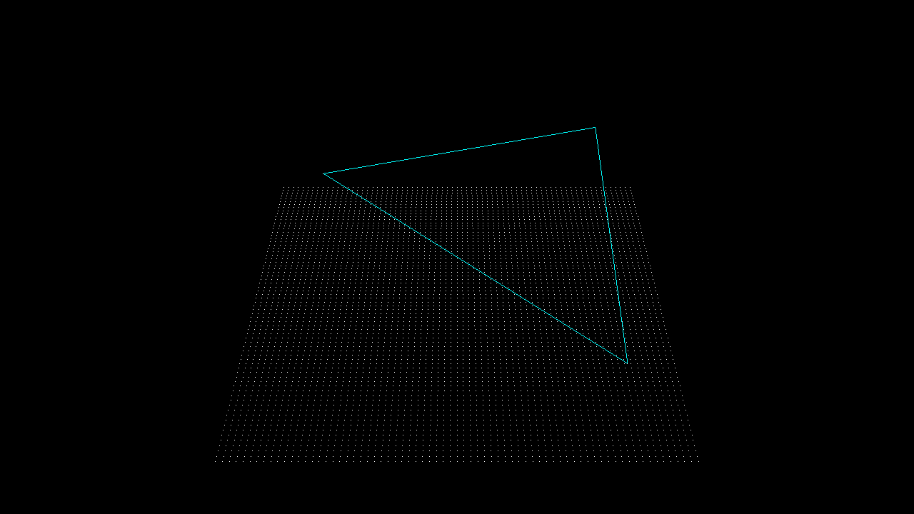
Now the problem of contacting a toroidal cutter with the facet of a triangle.

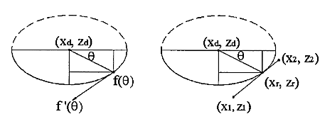
We need to find the equation of the plane which contains the triangle. If the triangle is defined by three points p1 = (x1, y1, z1), p2 = (x2, y2, z2), p3 = (x3, y3, z3) then a surface normal will be perpendicular to both p1-p2 and p1-p3:
N =
(NX, NY, NZ) = (p1-p3)x(p1-p2)
and it can be normalized to unit length by setting
n
= (nx, ny, nz) = N / sqrt(NX^2 + NY^2 + NZ^2)
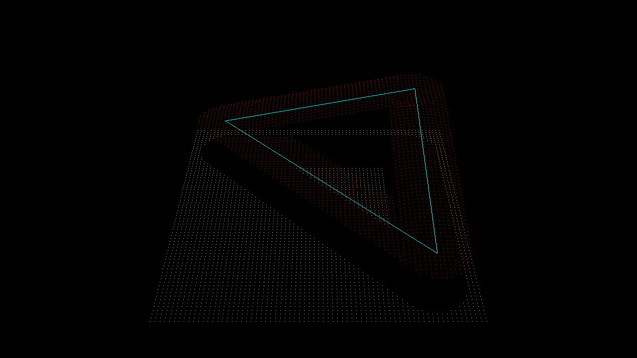
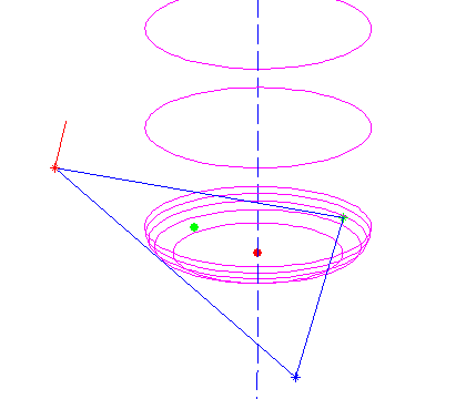
I've drawn a surface normal in red in the picture above.

Now the plane containing the triangle is given by
a x + b y + c z + d = 0
where (a, b, c) = (nx, ny, nz) and d can be found by noting that any of the points p1, p2, or p3 must satisfy the equation:
d = - nx*x1 -ny*y1 -nz*z1
the plane is going to make an angle theta with any vertical line, where theta = asin(c)

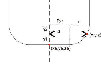
Then we need a new figure:

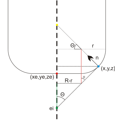
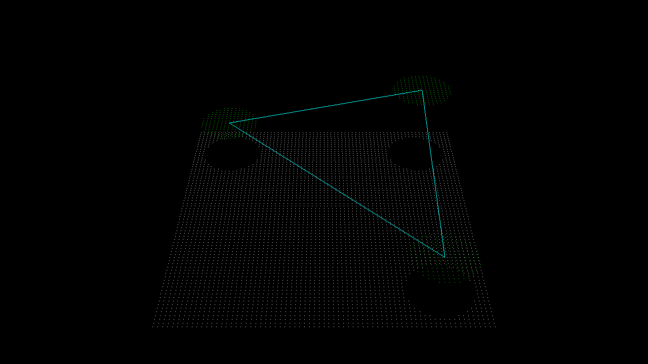
We start out at ei = (xe, ye, zi) , the point on the plane that intersects the line along which we're dropping the cutter (green dot above). It needs to satisfy the equation for the plane, so
zi = - (d + a xe + b ye) / c
Note: c=0 is a special case which needs to be handled separately.
from here we need to climb up to the correct ze, and that's done by first summing the green distance, then the red one, and then dropping down by r:
ze = - (d + a xe + b ye) / c + (R-r)/tan(theta) + r/sin(theta) - r

Now we have the cutter in contact with the plane, but we still need to check that the cutter contact point (CC-point, the blue dot above) is within the triangle facet and not some other point on the plane. To do that we need (x,y,z): If we start at the red point e = (xe, ye, ze) we get to he CC point by travelling upwards to the yellow point, and then along the normal down to the CC point:

CC = e + ( (R-r)*tan(theta)+r )k - ( (R-r)/cos(theta) +r )n

where k=(0, 0, 1) is a unit vector along the positive z-axis.

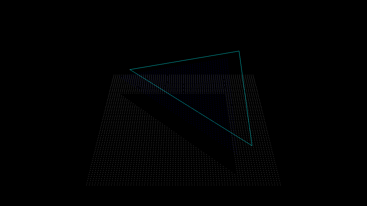
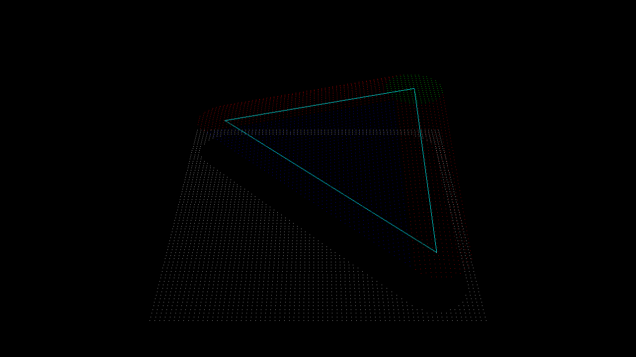
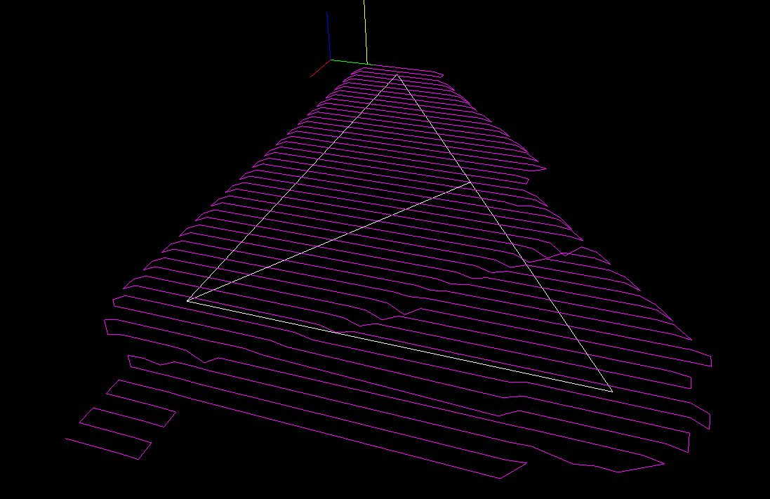
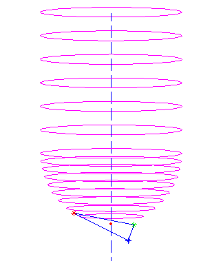
All of this seems to work as evidenced by the top picture where a toroidal cutter is brought into contact with a facet. The CC point is indicated with a green dot, and the CL (cutter location, or (xe, ye, ze)) point with a red dot.

Now we need to check if the CC point lies within the triangle, but that will have to wait until the next post... (Mr. Todd has some thoughts on this)

Drop Cutter part 1/3: Cutter vs. Vertex

Based on a 2002 paper by Chuang et al., I'm trying to understand the math for calculating 'drop-cutter' toolpaths (Julian Todd also has a lot to say about the drop-cutter approach). The basic idea is that the x,y position of the cutter is known, and it is dropped down along the z-axis until it touches a triangulated surface. A complex surface is built up of many many small triangles, but the algorithm stays the same.

For each triangle there are seven items the cutter might be touching: three vertices, three edges, and one facet (the triangle surface). It looks like a contact point with a vertex is the easiest to calculate, so I'm starting with that. I'm hoping to post part 2/3 and 3/3 of this post soon. They will deal with the facet and the edges.

I'm using this fairly simple cutter definition C(R,r) where R denotes the shaft diameter and r the corner radius. The three basic shapes that can be defined this way are shown in the picture. A more elaborate model would include tapered cutters, but I think I won't bother with that now... A cutter thus consists of a cylindrical part or a toroidal part, or both. That means I need six different functions in total for this algorithm:

  1. Cylinder against vertex
  2. Toroid against vertex
  3. Cylinder against facet
  4. Toroid against facet
  5. Cylinder against edge
  6. Toroid against edge

Here's how I think no 1 and 2 work.

Assume the vertex we are testing against is at (x, y, z) and say the cutter is at location xe,ye. We are looking for the cutter z-coordinate ze so at the end when the cutter is in contact with the vertex it will be located at (xe, ye, ze) .

Calculate the distance in the xy-plane from (xe, ye) to (x, y):
q = sqrt( (xe-x)^2 + (ye-y)^2)

Now if q > R the vertex lies outside the cutter and we should report an error or just skip to the next triangle/vertex.

If q <= R-r the vertex lies under the cylindrical part of the cutter and we set ze = z

If (R-r) < q <= R the vertex lies under the spherical/toroidal part of the cutter. This picture should explain the geometry:

The cutter can be positioned a distance z1 lower than z. To calculate z1 we need z2. It can be found by noting that (x ,y, z) should lie on the toroidal surface:
(q-(R-r))^2 + h2^2 = r^2
or h2 = sqrt( r^2 - (q-(R-r))^2 )
so now h1=r-h2 and we found ze = z-h1

A quick test in matlab seems to confirm that this works:

here a ball-nose cutter is dropped down along the dashed line into contact with all three vertices (red, blue, and green stars), and finally it's positioned at the highest ze found (red dot).

Well, that was easy. Now onto the facet and edge tests!