I've been reading about the z-map model for 3-axis milling. A working simulation environment would be very useful for CAM algorithm development. Coarse errors in the algorithms can be spotted by eye from the simulation, and a comparison of the z-map with the original CAD model can be used to see if the machining really produces the desired part within tolerance.
Jeff Epler hacked together a z-map model with EMC2 a while ago: gdepth. Perhaps some code/ideas can be borrowed from there.
The z-map can also be used for generating the tool paths themselves (similar to bitmap-mowing here, here and here), but that's more advanced and not the immediate goal.
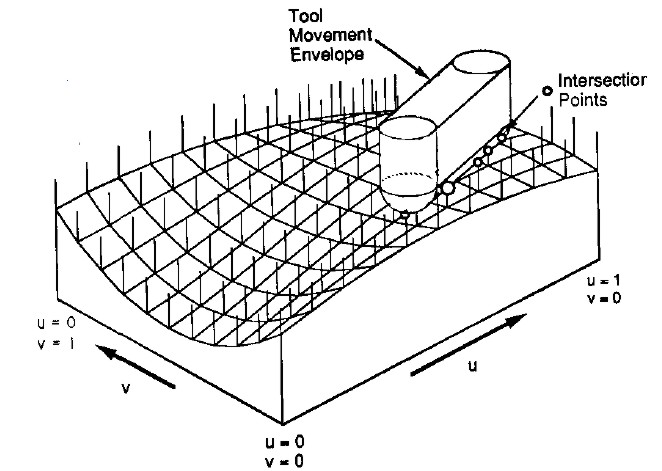
Here's the z-map model, a lot of vectors standing upright in the z-direction, getting cut (or mowed down) by the moving tool. For graphics you could fill each space between four z-vectors with two triangles and display an STL surface. Obviously this works only for 3-axis machining where the tool is oriented along the z-axis, and the tool must also not produce undercuts (e.g. T-slot milling).
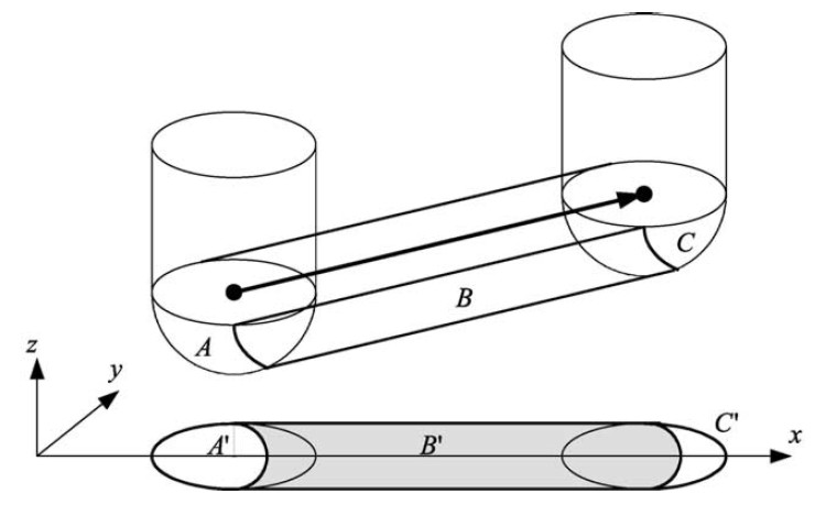
So how do you cut down the z-vectors for each move in the program? For linear moves you can always rotate your coordinate system so it looks like the figure above. The movement is along the x axis, with possibly a simultaneous move in the z-axis. At the beginning of each move (A) and at the end (C) it's very simple, you just calculate the intersection of the relevant z-vectors with a stationary tool at A and C, a kind of 'inverse drop-cutter' idea.
The surface the tool sweeps out during the move itself (B) is more difficult to deal with. The mathematics of the swept surface leads to an equation which most people seem to solve numerically by iteration. I'd like to go through the math/code in a later post (need to learn how to put equations in posts first!).
It's not smart to test all z-vectors in the model against the tool envelope of each move. So like drop-cutter where you are searching for which triangles are under the tool, in z-map you want to know which z-vectors are under the tool envelope. One strategy is simple bucketing, but perhaps if a kd-tree is developed for drop-cutter the same algorithm can be used for z-map.
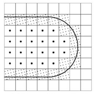
Obviously the z-map has a finite resolution. Increasing the linear resolution by some factor a requires a^2 more z-vectors, storage, and calculations. A better way might be to insert more z-vectors only where they are needed. That's the places on the model where the z-coordinate changes a lot. So here (view from above) for example if you are milling with a cylindrical cutter more z-vectors are needed along the edge of the tool envelope. (I have no idea why they are inserted in a tilted grid-pattern in the above figure...). This potentially leads to much reduced memory/calculation requirements, while still producing a high resolution model. As the simulation progresses there are probably also regions where some densely spaced z-vectors could be removed. Maybe a 'garbage-collector' process could go over the model every now and then and look for flat areas (xy-plane like regions) where less z-vectors are needed and remove them.
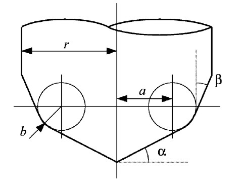
A lot of papers use this APT tool when deriving the equations for machining or simulations. By varying the parameters suitably you get the familiar tool shapes below:
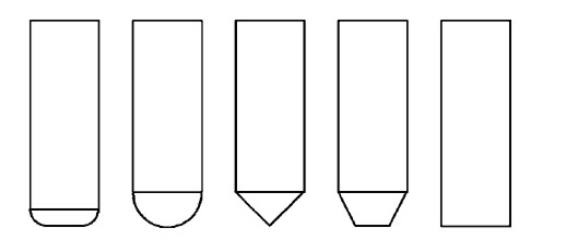
From left to right: Bull-nose/filleted/toroidal, Round/ball-nose/spherical, drill/countersink, tapered, and cylindrical.
My earlier drop-cutter explanations and code only work with the toroidal, spherical, and cylindrical cutters. I'm not sure if it makes sense to write the code for the general APT cutter, or if it's better to optimize for each case (cylindrical and spherical are usually quite easy).
If anyone has made it this far, my sources are the following papers - which are available from me if you ask nicely by email.
- Chung et al. 1998 (doi:10.1016/S0010-4485(97)00033-X): "Modeling the surface swept by a generalized cutter for NC verification"
- Drysdale et al. 1989 (doi:10.1007/BF01553878): "Discrete Simulation of NC Machining"
- Jerard et al. 1989 (doi:10.1007/BF01999101): "Approximate methods for simulation and verification of numerically controlled machining programs"
- Jerard et al. 1990 (doi:?): "The use of surface points sets for generation, simulation, verification and automatic correction of NC machining programs"
- Lee et al. 2002 (doi:10.1016/S0924-0136(02)00761-6): "Development of simulation system for machining process using enhanced Z-map model"
- Maeng et al. 2003 (doi:10.1016/S0010-4485(02)00161-6): "A Z-map update method for linearly moving tools"
- Maeng et al. 2004 (doi:10.1109/GMAP.2004.1290053): "A fast NC simulation method for circularly moving tools in the Z-map environment"
- Flutter and Todd 2001 (doi:10.1016/S0010-4485(00)00136-6): "A machining strategy for toolmaking"
Julian Todd is the guy behind the freesteel site.
A technique I was experimenting with (which may well be covered in some of the papers you cite, or be totally unworkable) for efficiently generating z-maps is to precompute what I call the "marginal impact profile" of the tool at position X given that it has already (or will) remove material from positions X-iota and X+iota with a specific height at each position. The marginal impact profile is much more limited than the full tool shape, so for the same CPU power you can compute a much higher resolution z-map than you could by removing the entire tool profile at each iota-step along the path.
Note that I believe z-map and drop-cutter are basically identical algorithms at their core. Both are a pseudo-convolution of a surface (the desired shape for drop-cutter, the toolpath for z-map) with a kernel (the tool shape), only (and this is the pseudo- part) where a true convolution would use an integral, here we are using the max (or min) operator: what is the maximum tool depth that does not infringe the desired shape (drop-cutter), or what is the minimum material depth that was not cut by any tool pass (z-map). Of course it's complicated in reality because g-code (or whatever toolpath representation you use) and STL (or whatever polygon mesh format you use) are very different ways to represent surfaces.
This is all too terse to make much sense, but I'm hoping you know it already and can tell me the proper names people use for the stuff I'm making up.
Yes, I am glad someone has spotted that zmap and drop cutter are the same algorithm. That puts you at greater understanding than most professors in the field.
The basic function is
dropcutter(triangle, tool, (x,y))
For a surface S, which is a set of triangles,
dropcutter(S, tool, (x,y)) =
max({dropcutter(triangle, tool, (x,y)) for all triangles in S})
This function is handy, because you can go and calculate it at any (x,y) you like when you need it.
The zmap idea is to pre-calculate the value of dropcutter on a regular grid of (x,y)s by running this maximization over all of them while looping through the triangles. So:
zmap = { regular set of points (x,y,z) initialized with z = -100 }
Then for each triangle in S:
zmap = { max(z, dropcutter(triangle, tool, (x,y)) for each (x,y,z) in zmap }
The reason why this is stupid is that (a) it uses a tonne of memory which is unnecessary, and (b) it gives a whole bunch of values where you don't want them.
Anyhow, I'm still waiting for you guys to start posting up thoughts on the structure of this algorithm on links from:
http://en.wikipedia.org/wiki/Computer-aided_manufacturing
Unlike blogs, wikipedia can handle mathematical equations. And I will contribute and work with people until they are got right.
I don't think wikipedia is really appropriate to be a primary repository of information, especially in-progress "thoughts".
The zmap you describe is a memoized dropcutter. The one Anders was describing is the simulated result of a toolpath. Different application (though still a very similar algorithm underneath).