Slight design changes to the RF Multiplexer design.
Slight design changes to the RF Multiplexer design.
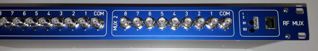
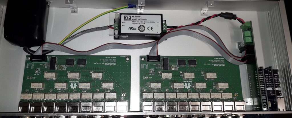
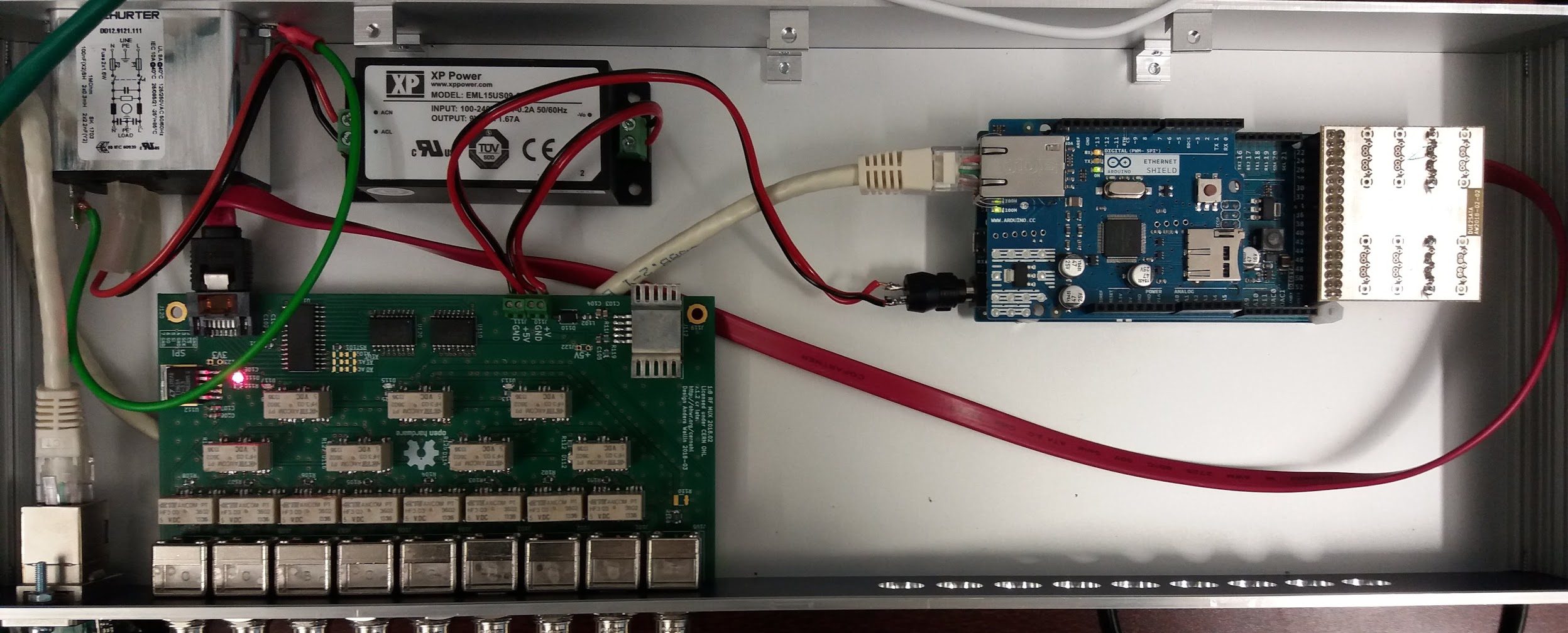
This is the third prototype for the 1:8 RF-multiplexer (https://www.ohwr.org/projects/rf-mux-8ch). The board is now simplified with only one 10-pin ribbon-cable attaching it to the Arduino MKR Zero + Ethernet shield. Traco PSU for 5V supply.
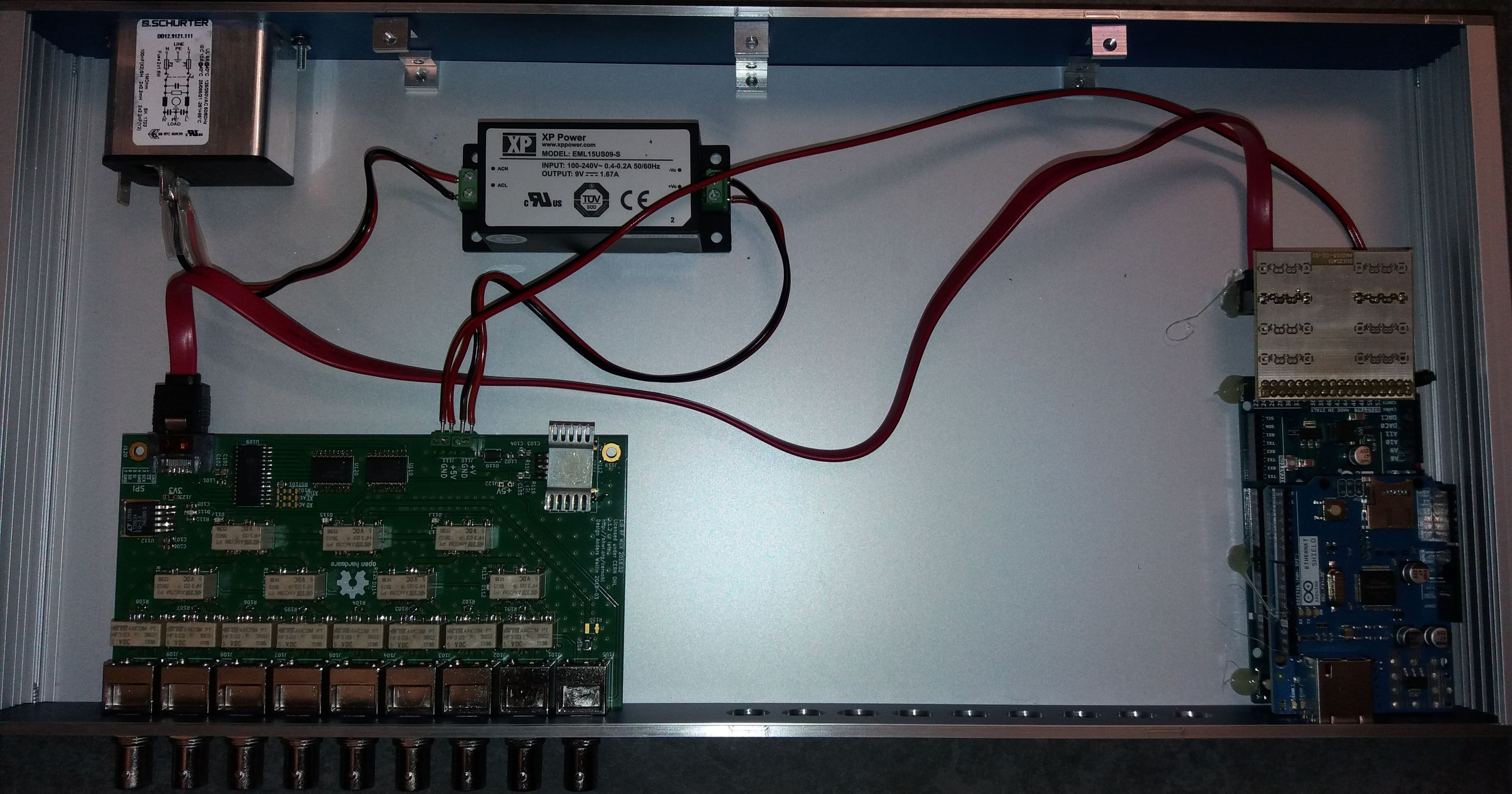
The second multiplexer prototyped, with a slightly larger enclosure placing the Arduino Due + Ethernet Shield directly in the front panel. This requires desoldering the DC-connector on the Arduino Due.
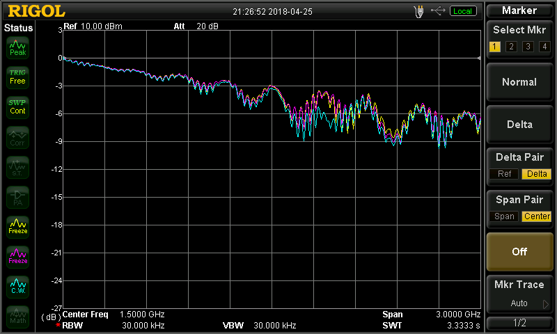
Bandwidth, insertion loss, and pulse-shape distortion measurements should be done next.
Update: Insertion-loss measurement with a spectrum analyzer:
RF-multiplexer v2 board in enclosure, controlled by Arduino Due with Ethernet Shield. SATA-cable for 4 SPI-lines (SI, SO, SCLK, CS).
When issuing commands to change state as fast as possible this combination seems to do a state-change in about 45 milliseconds - this is not verified on the RF-side (didn't measure that there is actual RF contact made/broken in those 45 ms).