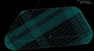
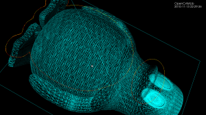
Inspired by this post on the pycam forum and by this 1993 paper by Luiz Henrique de Figueiredo (or try another version) I did some work with adaptive sampling and drop-cutter today.
The point based CAM approach in drop-cutter, or axial tool-projection, or z-projection machining (whatever you want to call it) is really quite similar to sampling an unknown function. You specify some (x,y) position which you input to the drop-cutter-oracle, which will come back to you with the correct z-coordinate. The tool placed at this (x,y,z) will touch but not gouge the model. Now if we do this at a uniform (x,y) sampling rate we of course face the the usual sampling issues. It's absolutely necessary to sample the signal at a high enough sample-rate not to miss any small details. After that, you can go back and look at all pairs of consecutive points, say (start_cl, stop_cl). You then compute a mid_cl which in the xy-plane lies at the mid-point between start_cl and stop_cl and, call drop-cutter on this new point, and use some "flatness"/collinearity criterion for deciding if mid_cl should be included in the toolpath or not (deFigueiredo lists a few). Now recursively run the same test for (start_cl, mid_cl) and (mid_cl, stop_cl). If there are features in the signal (like 90-degree bends) which will never make the flatness predicate true you have to stop the subdivision/recursion at some maximum sample rate.

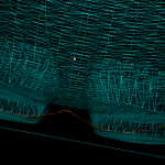
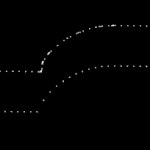
Here the lower point-sequence (toolpath) is uniformly sampled every 0.08 units (this might also be called the step-forward, as opposed to the step-over, in machining lingo). The upper curve (offset for clarity) is the new adaptively sampled toolpath. It has the same minimum step-forward of 0.08 (as seen in the flat areas), but new points are inserted whenever the normalized dot-product between mid_cl-start_cl and stop_cl-mid_cl is below some threshold. That should be roughly the same as saying that the toolpath is subdivided whenever there is enough of a bend in it.
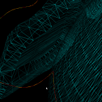
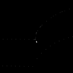
The lower figure shows a zoomed view which shows how the algorithm inserts points densely into sharp corners, until the minimum step-forward (here quite arbitrarily set to 0.0008) is reached.
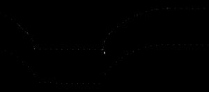
If the minimum step-forward is set low enough (say 1e-5), and the post-processor rounds off to three decimals of precision when producing g-code, then this adaptive sampling could give the illusion of "perfect" or "correct" drop-cutter toolpaths even at vertical walls.
The script for drawing these pics is: http://code.google.com/p/opencamlib/source/browse/trunk/scripts/pathdropcutter_test_2.py
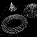
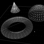
Here is a bigger example where, to exaggerate the issue, the initial sample-rate is very low:
