Update: In the US, where they are silly enough to have software-patents, there's US Patent number: 7831332, "Engagement Milling", Filing date: 29 May 2008, Issue date: 9 Nov 2010. By Inventors: Alan Diehl, Robert B. Patterson of SURFWARE, INC.
Any pocket milling strategy will have as input a step-over distance set at maybe 10 to 90% of the cutter diameter, depending on machine/material/cutter. Zigzag and offset pocketing paths mostly maintain this set step-over, but overload the cutter at sharp corners. Anyone who has tried to cnc-mill a hard material (steel) using a small cnc-mill will know about this. So we want a pocketing path that guarantees a maximum step-over value at all times. Using the medial-axis it is fairly straightforward to come up with a simple pocketing/clearing strategy that achieves this. There are probably many variations on this - the images/video below show only a simple variant I hacked together in 2-3 days.
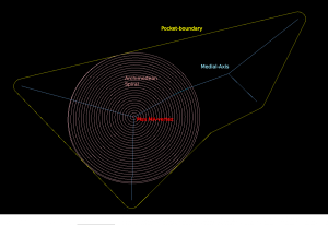
The medial-axis (MA, blue) of a pocket (yellow) carries with it a clearance-disk radius value. If we place a circle with this radius on the medial-axis, no parts of the pocket boundary will fall within the circle. If we choose a point in the middle of an MA-edge the clearance-disk will touch the polygon at two points. If we choose an MA-vertex of degree three (where three MA-edges meet), the clearance-disk will touch the pocket at three points.
MA-pocketing starts by clearing the largest clearance-disk using a spiral path (pink).
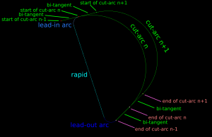
From the maximum clearance-disk we then proceed to clear the rest of the pocket by making cuts along adjacent clearance-disks. We move forward along the MA-graph by an amount that ensures that the step-over width will never be exceeded. The algorithm loops through all clearance-disks and connects the arc-cuts together with bi-tangents, lead-out-arcs, rapids, and lead-in-arcs.
This video shows how it all works (watch in HD!). Here the cutter has 10mm diameter and the step-over is 3mm.
I'll try to make a variant of this for the case where we clear all stock around a central island next. These two variants will be needed for 3D z-terrace roughing.


thanks a lot for taking the time to document this path strategy in such a detail - that's great!
Regarding the archimedean spiral (and the additional arc-cuts): can they be expressed in arcs or quadratic B-splines? (for GCode: G2/G3 or G5.1)
To put it differently: will opencamlib return line segments or more complicated geometrical descriptions?
(as soon as opencamlib offers this algorithm)
Just curious ...
cheers,
Lars
Hi Lars,
Currently all moves are G1 moves, because that makes the simulator show everything nicely in "slow motion".
The spiral can certainly be approximated with G2/G3 arcs. One would then input also an approximation tolerance. I don't know if it could be represented exactly with G5.1 (B-spline) or G5.2/3 (Nurbs). At least LinuxCNC has these G5-codes but I'm not sure how standard they are on other controllers.
After clearing the initial circle (either using an archimedean spiral, or something else), the toolpath consists of the cut arcs (G2/3), bi-tangent segments (G1), and lead-in/out+rapid to next bi-tangent.
This is a C1 continuous path, i.e. the tangent of the toolpath is continuous. In the literature there are people arguing that C2-continuous paths would be even better for machine with very high dynamic capacity (acceleration and jerk). A C2-continuous path has continuous radius of curvature (i.e. smooth acceleration of machine). This can be achieved e.g. with a trochoid. I think one could use the current cut-arcs to limit how much the trochoid cuts on each "scoop".
During the rapid-move to the next cut-move the tool can/should be lifted so that it doesn't scrape the bottom of the already cleared pocket. This can be a "micro-lift", i.e. 0.1 mm or similar. I think it make sense to have the lead-in/out arcs actually be helices where on lead-out we do the micro-lift to Z=+0.1 and on lead-in we do a helix down to Z=0 again.
Next I'll be working on getting this strategy functioning with arbitrary pockets, and also for "external" clearing (i.e. when we clear all of the stock except a central island).
Anders
Hi Anders,
thanks for the good amount of details and your patience again!
I am also not sure about the availability of B-splines and nurbs in other GCode interpreters besides LinuxCNC. Thus maybe it is better to focus on approximated arcs or linear moves instead.
Regarding the G1/G2/G3 moves: do you already know, which kind of information opencamlib will return for this example?
I guess, that I will try to use opencamlib's functions within PyCAM quite soon. Thus I would like to know, if I will need to handle arcs in the near future ...
Keep on the good progess!
Lars
Yes, G0/1/2/3 will definitely be standard output at some point.
If there are higher-level algorithms that can only deal with polygon input then an "only G0/G1" mode might be sensible to have.
G5.x will not be a priority for now.
AW
I notice that you have three milling spirals to that design. Why can't you make it all one spiral and for the odd extra cuts needed just go back and finish them. What I met for odd extra cuts it lets say one inner edge point (a) to center point is 42 passes to complete and the other inner edge point is 50 passes to complete. After the 42 pass it goes to complete the 8 extra passes. I think it'll make the process better and faster. The reason I'm telling you is that I don't know how to code yet except some g-code and like to hear what you think. thanks
Hi John,
Ordering the cut-arcs in a different way is certainly possible. One advantage of the simple strategy shown above is that the rapid-move to the next cut-arc can be done with the tool down (or possibly a micro-lift). This is because the rapid is contained within the previous cut-MIC which we know is cleared of material.
With another order of the cut-arcs, if/when you start to have cut-arcs that are e.g. on opposite sides of an oval pocket one needs to be careful with the rapid-move between the cut-arcs. In general one would have to lift the tool to a clearance-height to avoid collisions.
The strategy I now use cuts all cut-arcs belonging to an edge of the medial-axis in one go. If one wanted to alternate between edges (i.e. different ends of an oval pocket) then one needs to keep track of ma-edges that are partially done.
I think the cut-arcs could in fact be represented as a DAG (directed acyclic graph, similar-ish to a tree). In this tree my current simple strategy is a depth-first-search
http://en.wikipedia.org/wiki/Depth-first_search
while the one you are suggesting is more like a breadth-first-searc
http://en.wikipedia.org/wiki/Depth_first_search
One could possibly alter between DFS and BFS also (e.g. in order to minimize the overall distance of rapid-moves).
Overall I think the medial-axis can be used for many different area-clearing strategies. It's a shame that my library isn't connected to a good GUI yet. I'd like to see it working from FreeCAD at some point.
Anders
That looks awesome!
I need to get my step-by-step simulation going so you don't have to resort to 2D.