I made two small circuits today for temperature control of the extruder head on a reprap type 3D printer. The idea is to control the temperature, which needs to be somewhere between 200 and 240 C I think, using EMC2 and two parallel port pins.
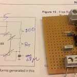
The first circuit is based on the 555 and produces a square waveform with variable frequency depending on the resistance of a thermistor. At room temperature the thermistor resistance is 100 kOhms and the output frequency is below 1 Hz, and when the temperature is suitable for extrusion the thermistor resistance is about 200 Ohms which produces an output frequency of around 25-30 Hz. If the EMC2 base-thread runs with a 50 us period then it should be possible to record the frequency of this square wave using an input pin on the parallel port with an accuracy of roughly 1/500 (half a degree C?), which should suffice.
Testing the heating side of things, a wire with about 6 ohms of resistance wrapped around the extruding head, showed that a suitable DC voltage is around 8 V and produces a current of 1.3 A. The idea is to use a HAL PWM-generator to drive the base of a 337 transistor which drives the gate of an IRF610 FET that controls the current through the heating wire. By adjusting the PWM duty cycle it should be possible to control the temperature using a PID controller based on the temperature measurement.
The FET is now changed to an IRFZ44 which has much lower RDS_ON and does not require a heat-sink.
Anders, I intend to build the circuits you developed to use with LinuxCNC. I am not able to determine some of the values, due in part to my old eyes not being able to see the color coding on the resistors, and not able to discern some of the writing from your pictures.
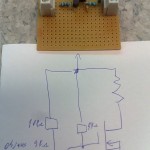
I have made a schematic as best as I understand the circuitry, and have left out the values that are missing. I have obtained the components that I am able to identify and presently am inserting those components in a bread board. On the picture of the timer circuit there is a grey rectanular box that I am not familiar with nor its value and there are 4 resistors in the picture but only 3 called out on the sketch of the heater circuit. I would appreciate your review of the schematic that I made and request that you make any corrections or obvious errors before I start soldering as well as provide the values to the resistors that are unknown to me presently. I would value your input and suggestions greatly as well as any modifications that you would make. Please let me know.
Thank you in advance.
Mike Maxfield
The breadboard I was using has conducting copper-stripes on the back side. These conduct along one direction of the board, e.g. X-direction. When I wanted conducting paths along the Y-direction I have used either jumper-wires (silver color in the picture), or zero-ohm resistors (these are beige with a single black stripe).
The grey component is probably the a 100nF capacitor from Vcc (pins 4 and 8) to ground (drawn by hand on my schematic). This is called a "decoupling capacitor" and is used next to Vcc close to any IC chip.
I'll admit that the drawing of the heater-circuit is very bad. The main idea however is to take a PWM output from linuxcnc and use that to turn on/off a single FET that applies a (big) voltage across a heating-resistor. There are many ways to do this and my circuit is just one way. google with "pwm heater FET switch" will probably give lots of results.
Anders
Anders, I would like to thank you for all your assistance and help that you have given to Mike Maxfield. Mike has been a great help to me with this project. P.J.
Hi,
I would like to do the same on my CNC
unfortunately, I'm not able to integrate
the pid control panel into LinuxCNC.
I tried, by trial and error method,
but it was only error....
Would you like to drive me to install
this panel tool
What I have to do with the four files you gave on the other link.
Regards,
Hi, Again it's me.
To be more clear, I Have the interface integrated into LinuxCNC,
but when I try to "connect" the hal I have some errors.
The last try I did,
after many handling,
it rest some errors, like:
can not find -sec MOT -var MOT -num 1
can not find -sec IO -var IO -num 1
can not find -sec LINUXCNC -var NML_FILE -num 1
can not find -sec EMC -var NML_FILE -num 1
custom.hal:4 Pin 'pyvcp.temp-freq' does not exist
( I copied colled, the reprap_to_pyvcp.hal's content into custom.hal )
Please I really need your help on this problem.
I can send you my files if you want.
Believe me, I'm absolutely not used to work on linux, and not python or similare scripting coder,
I read again and again, passed a lot of white night before to ask your help.
I'm on it since few weeks.
My best regards.
Hearty: the fastest way to get help is usually the #linuxcnc IRC-channel
The mailinglist also works quite well.
I can try to look at setting this up in a simulator-build of linuxcnc on my home machine over the weekend - if I find time...
AW
Hi,
first of all, thanks for answer.
You have to know that I'm French,
so I have some difficult to talk directly in english
I need to think a lot before to say in English what I have to say.
It's better for me via mail, I have the time to ask, read, and understand.
Can you send me a mail, I will send you by return my config files.
I need just a way to solve this last mistake which stop this exciting project.
Regards,
Hearty now has a circuit diagram online:
http://heartygfx.blogspot.fr/2012/11/repstrap-cnc-sous-linuxcnc.html