The DSM system by Spektrum RC (www.spektrumrc.com) is a new and exciting development.
I got my RF-module and receiver ahead of the radio that I have also ordered so I have time to inspect the DSM parts before trying them out...
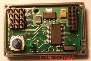
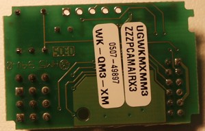
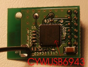
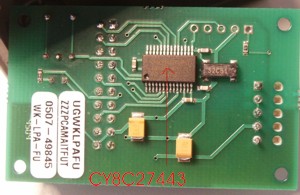
Receiver
The lower card:
The upper card:
There are essentially two ICs with a bit of gluelogic in-between.
Closest to the antenna, on the "upper-deck" PCB, there is a Cypress semiconductors CYWUSB6934. From the datasheet:
"The CYWUSB6932/CYWUSB6934 Integrated Circuits (ICs) are highly integrated 2.4-GHz Direct Sequence Spread Spectrum (DSSS) Radio System-on-Chip (SoC) ICs. From the Serial Peripheral Interface (SPI) to the antenna, these ICs are single-chip 2.4-GHz DSSS Gaussian Frequency Shift Keying (GFSK) baseband modems that connect directly to a microcontroller via simple serial interface."
- 2.4-GHz radio transceiver
- Operates in the unlicensed Industrial, Scientific, and Medical (ISM) band (2.4 GHz-2.483 GHz)
- -90-dBm receive sensitivity
- Up to 0 dBm output power
- Range of up to 10 meters or more
- Data throughput of up to 62.5 kbits/sec
- Highly integrated low cost, minimal number of external components required
- Dual DSSS reconfigurable baseband correlators
- SPI microcontroller interface (up to 2-MHz data rate)
- 13-MHz ± 50-ppm input clock operation
- Low standby current < 1 µA
- Integrated 30-bit Manufacturing ID
- Operating voltage from 2.7V to 3.6V
- Operating temperature from 0° to 70°C
- Offered in a small footprint 48 Quad Flat Pack No Leads (QFN)
- about 6 USD in larger quantities
Reading the datasheet it seems that this chip does not contain very much "intelligence". You input the data you want to send on the SPI bus and then this IC transmits the data (with settings set by various other pins).
On the lower-deck, closer to the servo inputs there is a Cypress semiconductors CY8C27443. This is the brain of the receiver, it's a microcontroller which also has some analog circuitry onboard. Features include (complete datasheet available from the Cypress website):
Powerful Harvard Architecture Processor
M8C Processor Speeds to 24 MHz
8x8 Multiply, 32-Bit Accumulate
3.0 to 5.25V Operating Voltage
Industrial Temperature Range: -40°C to +85°C
Advanced Peripherals (PSoC Blocks)
Up to 14-Bit ADCs
Up to 9-Bit DACs
Programmable Gain Amplifiers
Programmable Filters and Comparators
8 Digital PSoC Blocks Provide:
8- to 32-Bit Timers, Counters, and PWMs
CRC and PRS Modules
Up to 2 Full-Duplex UARTs
Multiple SPI(TM) Masters or Slaves
Precision, Programmable Clocking
Internal 2.5% 24/48 MHz Oscillator
24/48 MHz with Optional 32 kHz Crystal
Optional External Oscillator, up to 24 MHz
Internal Oscillator for Watchdog and Sleep
Flexible On-Chip Memory
16K Flash Program Storage 50,000 Erase/ Write Cycles
256 Bytes SRAM Data Storage
In-System Serial Programming (ISSP(TM))
Complete Development Tools
Free Development Software (PSoC(TM) Designer)
Full-Featured, In-Circuit Emulator and Programmer
Full Speed Emulation
Complex Breakpoint Structure
128K Trace Memory
Cost ca 3 USD in large quantities
Very nice that the compiler and software develompent kit are available for free ! How long before someone makes an Open Source DSM receiver/transmitter system ? 🙂
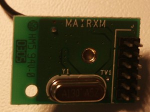
TX Module
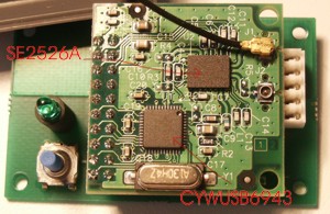
This is also a double-deck design. The lower card has the same CY8C27443 microcontroller and a LM2937 3.3V voltage regulator + the LED and the bind button.
The upper card also has the same CYWUSB6943 RF-chip but in addition there's a SiGe semiconductors SE2526A 2.4GHz Power Amplifier:
Dual Mode IEEE802.11b & IEEE802.11g
All RF ports matched to 50 Ω
Integrated PA, TX Filter, T/R and Diversity switch
Integrated high performance power detector
20 dBm O/P Power, 802.11b, 11 Mbps @ 225 mA and ACPR-1 = -37 dBc, ACPR-2 = -56 dBc
18 dBm O/P Power, 802.11g, EVM = 2.5 %, 54 Mbps @ 185 mA
Single supply voltage: 2.7 V to 3.6 V
Exceptional temperature stability
Small MSL3 package (5.5 mm x 7.0 mm x 1.2 mm)
cost about 2 USD in large quantities.
Conclusions
The TX module uses a CY8C27443 microcontroller (2 USD) which receives commands from the transmitter and sends them on to the CYWUSB6934 (ca 6 USD ?) which transmits them using the DSSS system on 2.4 GHz. To boost the signal there is a SE2526A (2 USD) power amplifier before the antenna.
I wonder why there are two coaxial antenna outputs on the TX module ?
Update 2005 Jun 3:
A fried of mine explained this: WLAN (WiFi) chips and base stations typically have two antenna outputs and two antennas to eliminate multipath fading i.e. interference effects in urban environments that cause loss of signal. If you have two transmitting antennas half a wavelength apart then that eliminates this kind of fading. (you use only one of them at a time, always choosing the better one)
The RX is a simplified version, leaving out the power amplifier. This is probably why binding only works at close range. During the binding process the RX sends back stuff to the TX and this works only at short range since there is no power amplifier in the RX.
So, taking advantage of chips that were probably developed for WLAN use, there is about 10 USD of parts in the TX module and ca 5 USD worth in the RX. This together with some fancy software makes for a great system ! (sold at 160 USD...)
The similarity of the RX antenna connection to the coaxial connector mounted on the TX module suggests that it could be possible to fit a coaxial cable also on the RX and have a normal WLAN antenna some way away from the RX. I think I will have to try this...
Do you know the pinout for the transmitter? I need to know the which pins are the ppm, vcc, and gnd. Thanks
Hi,
Sorry I don't know the pinout for the Tx module. If there are only three pins then it should be quite easy to measure where vcc and gnd are with a multimeter but you would probably need an oscilloscope to confirm where the ppm signal is.
Do you know what the standard ppm protocol for R/C TX's is ? I understand the Spektrum module works just fine even with radios it was not designed for...
Anders
I have a mulitplex 707 with a dcs cord. The dsc cord has vcc, ppm and gnd. I want to plug that into the spektrum transmitter module. I have not purchased the module yet. I just need to know which pins are which and which module to buy(JR or Futaba). I know the DSC cable works for Novak FM receivers. So do I buy a JR transmitter module? Thanks for your help.
Hi again Jose,
intrigued by your question I took a closer look at the Tx module. Look at the picture above:
http://www.anderswallin.net/wp-content/2005_05/TX_1.jpg
the connector which connects the module to the Tx is on the right, the five holes in a vertical column.
call the top pin nr 1 (if you look closely you see that the pad is square on this one) and the bottom one nr 5.
By looking at the PCB I think I can say that
1: most probably NC (not connected)
2 and 3: GND (pcb traces lead to the 'heatsink' of the LM723 regulator)
4: +V (pcb trace leads to input pin of regulator
5: signal (pcb trace leads to microcontroller)
This is the Futaba version of the module. I don't know what differences there are between JR and Futaba - could be only the connectors.
Let me know how your project goes !
Anders
how much does it cost (transmitter and receiver)?
Hi Noha,
check out the prices in a hobby store, http://www.horizonhobby.com/ for example.
The DSM receiver and module for a futaba systems seems to be around $180 at the moment.
Anders
hi noha
looking at the se2526A chip i see on the pc board that pin1 (leftside top) its not connected this is the pin for PA enable(power Amp)
Q1:do i connect it at vcc or gnd
Q2:does this give me more than 10mw
greets
Rolf,
I've sold the Futaba 3VCS and the Spektrum module so I can't look at them anymore.
If it's an enable pin for the amplifier then it must be connected. You should be able to figure out if it goes to ground or vcc by reading the datasheet.
that's all I can help with for now,
Anders
Ps. maybe I should rip open my new DX6 + Rx also to see what's inside them. And some people are getting the new Futaba 2.4GHz stuff now also - I need to convince them to let me open up everything and have a look.
Hi Anders,
I-m looking at the possibility of interfacing a Spektrum receiver, probably the AR7000 to a microcontroler based flight stabilisation system. One of the two systems available for my use at the moment (http://www.mikrokopter.de/) wants to receive a single PPM datastream, not the demultiplexed separate servo outputs. Would I be correct in assuming that the three pints for the receiver connectors actually are GND, V, and signal, and that the signal would be the PPM datastream as seen by that receiver. If that is the case, would the processor be looking at these two datastreams and choosing the best one, demultiplexing that, and providing it on the servo outputs, but not providing the PPM stream chosen?
As an additional question, would the system be as uncritical of increased numbers of channels being fed in to the Tx and being received with respect to the PPM stream as normal FM systems? For the above system, the most used Rx actually only outputs 3 servo channels, but the exported PPM stream will have as many channels as transmitted.
Thanks up front for your reply.
Hi Arthur,
I'm not sure I'm qualified to answer all your questions... sorry 🙂
In your first question, if you are talking about the three connectors for servos, then yes they are GND, V, and Signal. But as far as I know the signal that goes to the servos is PWM (Pulse Width Modulation), not PPM (Pulse Position Modulation). There is a positive going pulse every 50 Hz or so. If I remember correctly a pulse length of 1.5 ms corresponds to the middle position of the servo and the two extremes are about 0.5 and 2 ms respectively.
If you are talking about some internal connections within the receiver (for example between the RF stage and the servo outputs) then I doubt that Spektrum would use a PPM scheme for internal communication between the two processors. I do remember that some traditional radios on 35 or 40 MHz use a PPM modulation for the RF datalink, but I don't know much about this - sorry.
hope this helps,
Anders
With the three pins I was referring to the little cable between the AR7000 satelite receiver and the main body, and also the little receiver within the main body and the processor board.
Actually I have been looking at the product sheets for the transmitter and receiver chips used in the DX system. There are actually microprossors which have either I2C or SPI ports. So it could be that they output a digital stream to the microcontroler on the main deck which then translates that back to PWM modulated servo signals. I-ll have to look into that a bit further as this could be a significant simplification for my purposes. Why translate bytes to PPM / PWM and then translate back again ;=))
In fact if my supposition is right and the same would be the case at the TX end this would open up vast opportunities of insterting a microcontroler into the transmitter case which adds a few switchs to the case and resultant bytes into the data stream on the I2C bus and thus adds some channels
Within the transmitter there is certainly a PPM stream going from the human interface part into the transmitter proper. That is why it is possible to move the transmitter proper into a different (older) transmitter and get it to work like a DX6 or DX7. But most likely they do translate it into a byte stream in the microcontroler/transmitter stage.
I came accross this publication on the Cypress site behing the CYWUSB6935LR (= long range, 50m) specs which describes the different binding mechanisms which are possible between the CYWUSB693x devices. Interestingly the link from the CYWUSB6934 page doesn't work.... maybe a bind issue with Spektrum DSM ?=)
Another part of the Spektrum DX puzzle.
With respect to the pinouts for the CYWUSB6934 see http://download.cypress.com.edgesuite.net/design_resources/datasheets/contents/cywusb6934_8.pdf. SPI interface: Pin 22 = slave select, 23 = MOSI, 24=MISO, 25=SCK.
RF interface: Pin 5= RF out, 46=RF in.
The device does not have a I2C interface. Both satelite receiver boards actually has two chips, one numbered CYRF693?, the other CY8C214. Can't immediately found out what the latter is, but I assume it is taking the SPI output and translating the data onto a single bidirectional channel. as somehow between the little satelite receiver for the AR7000 and the processor in the main receiver they do switch from 6 wires (Vcc, MOSI, MISO, SCK, SS, GND) to a 3 wire connection (Vcc, GND, and ??).
Got a Parallax USB oscilloscope today and did some testing on the AR7000. On the little satelite board with the receiver the two pins closest to the side are indeed V and GND (didn't really check the order). The third pin is the more interesting. That in is definitely digital. So there is indeed a serial line between the transeiver board and the main board. So the large chip under the little satelite board must be receiving the two digital strings and doing some work on those to get transform the correct bytes to PWM signals on the servou outputs. the servo outpts are clearly standard PWM and change width with stick movements. The most interesting output however, is the power connector. Here the signal pin shows a series of 7 spikes. However, the total duration of this signal is very short, about 700 microseconds, each spike being probably about 15 microseconds long. It is very close in sync with the start of the PWM signal on channel 1. Any ideas ?
Just wondering what you would use to boost the output of ths DSSS signal from the Spektrum transmitter. I'd like to push the range further for FPV flying. I was considering a WLAN amp but they arent really designed for constant transmitting.
Any suggestions would be greatly appreciated?
Hi Roly.S,
There are omni directional antennas with at least +5 dBi gain, maybe more.
I just got an advertisement for a new TI chip "CC2591", maybe you could use that?
http://www.ti-estore.com/Merchant2/merchant.mvc?Screen=PROD&Product_Code=CC2591EMK
I have no idea if it's legal to boost the output power 100-fold, you'll have to check that yourself!