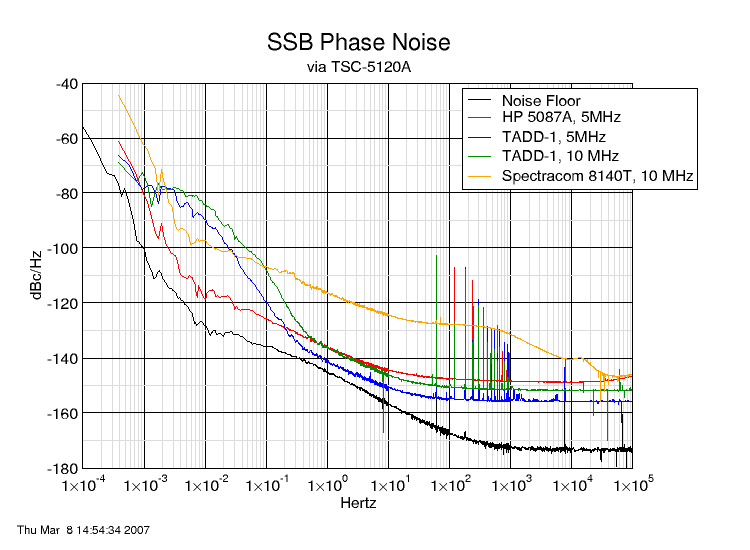
We need a number of frequency distribution amplifiers in the lab. Let's not reinvent the wheel but rather do a face-lift for the TADD-1. John Ackermann has phase noise measurements on the TADD-1 and TvB has temperature coefficient results on the TADD-1.
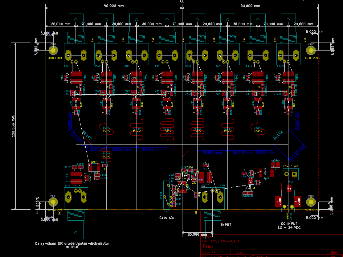
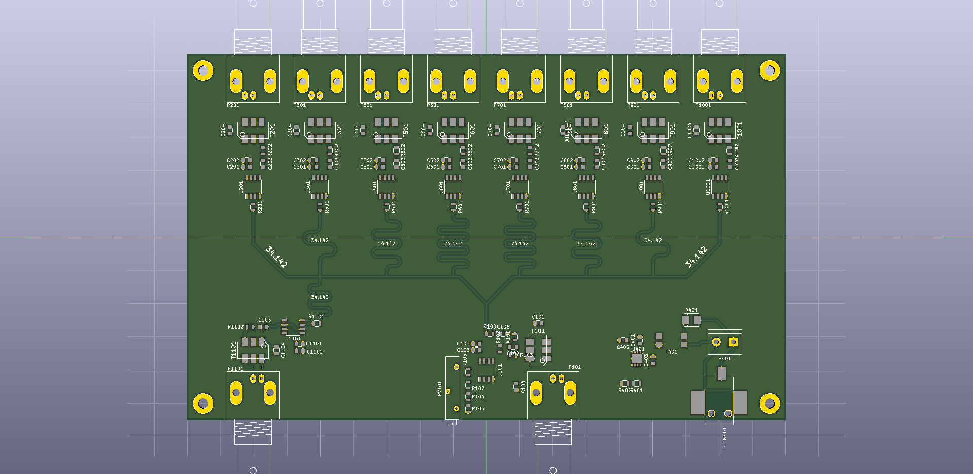
Here's a draft design for an SMD version of the TADD-1 frequency distribution amplifier. The plan is for a 2-sided 180 mm x 110 mm PCB. Two of these could be mounted side by side in a 1U 19" enclosure to give 2x8=16 outputs on the front panel. If a companion pulse distribution (1-PPS) board is built, the output at the back of this board can be used to drive a PICDIV on the pulse-distribution board. This gives 8 frequency outputs and 8 pulse outputs on a 1U 19" panel. The 2-pin connector at the DC-input can be used to power the other board in the same enclosure.
Comments? Suggestions?
- What causes phase-noise (drift) below 1Hz offset frequency in this graph?
- The original TADD-1 used a MAX477 and the update in 2007 used an AD8055. Are there newer and better op-amps?
- We need a good low-noise linear regulator circuit (lower right corner). Suggestions? (what's inside an Abracon ABPSM-ULN-A?)
PDF files: