Mowing tactics

Moving forward with the CAM coding, the sensible thing would probably be to work on mundane things like 2D offset generation, a kd-tree for faster drop-cutter searches, and zigzag-paths from 2D outlines... There's again been some talk about open-source CAM on cnczone, but not much in terms of results or actual descriptions or implementations of toolpath algorithms.

Anyway, here's something more fun than the traditional computational geometry problems I referred to above. It's lawn-mowing tactics, or how do you program the circular robot to mow the red pixels while not cutting too many of them at a time. This is a slightly improved version of my earlier trial. This one considers a number of angles in all directions for each move. From these moves the ones that cut away a suitable amount of material are selected. Additionally I've introduced a cost function for changing direction, it should be easier for the cutter to continue traveling in approximately the same direction than to do abrupt turns. In spite of this, about half-way through the cutter reverses direction...This is obviously done with a bitmap representing the grass to be mowed, but I wonder if it would be better to try to do it more exactly: represent the boundaries of the grass with lines and arcs. A variable step-length also seems like a good idea, on long straight bits the cutter should be able to move in one go as far as it goes.
Drop-Cutter in C# - v2

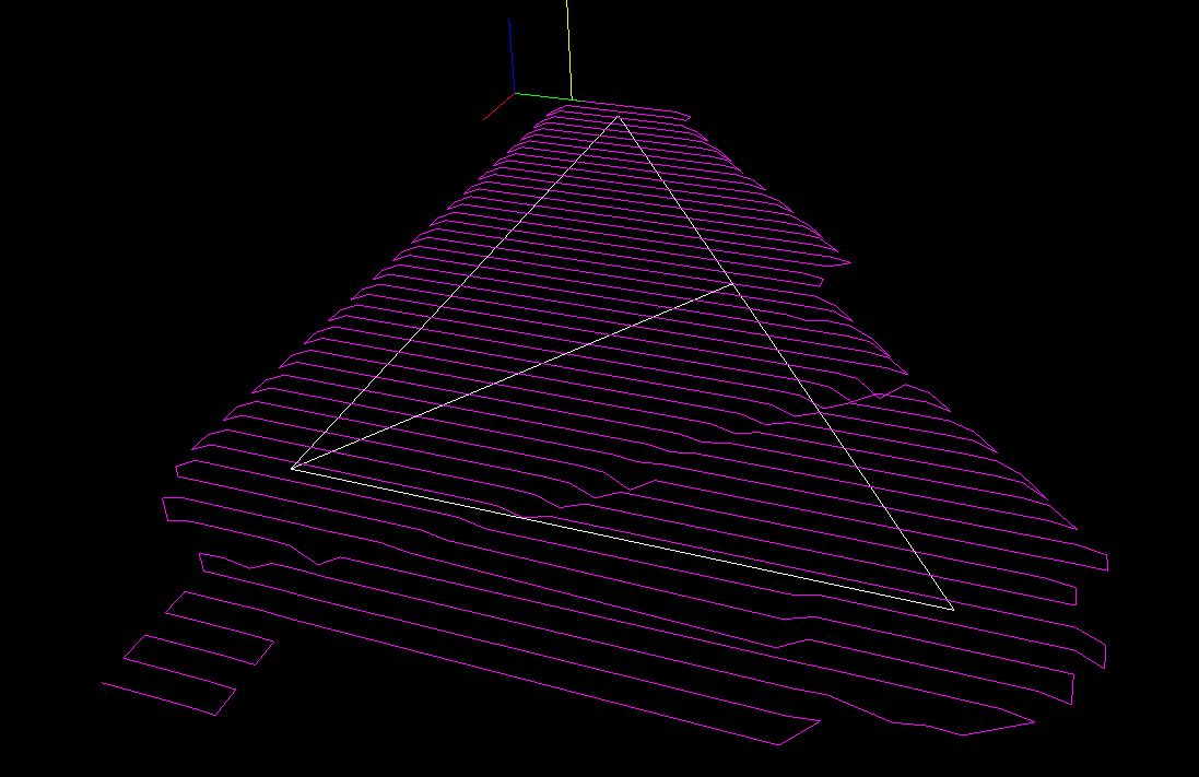
I think I've found the problems with my C# drop-cutter algorithm. The first bug was a trivial one where in the edge-test the rotation of the segment-under-test was messed up. The second one was not the facet-test itself but incorrect surface normal data. There's something going on that makes pre-calculated surface normal data not 'stick' correctly to the triangle object for later use. So here I'm re-calculating the normal data again just before the facet test.

The next step is to speed up things with a smarter kd-tree based search for which triangles are under the cutter. I've added bounding-boxes to the Cutter and Triangle classes. Running the above example the DropCutter function is called a total of 4735000 times, and of those only less than 5%, or 236539 to be exact, are useful calls, i.e. the triangle bounding box intersects the cutter bounding box, which means there's a chance that we are contacting the cutter against the triangle. The idea with the kd-tree then is to pre-search for triangles under the cutter to make less of those (supposedly expensive) redundant calls to DropCutter.

On my T5600 processor machine the above example runs in about 5 seconds. (1894 triangles, about 4.7 Million calls to DropCutter of which ca 240k calculate something). I've made a list of useful CAM-related things to work on: CAMToDo.

Drop-Cutter in C#

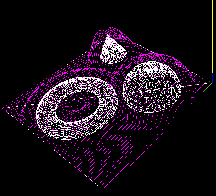
I've now ported my Matlab work on Drop-Cutter to C#. It can load an ASCII STL file and then run the drop cutter algorithm. Not trying to take too much on in the beginning, here's an example of the output with only two triangles as input 🙂 not quite there yet! (who can spot what's wrong?)

I'll do some nicer demos when I've found the problem. The algorithm runs significantly faster in C# compared to Matlab - and this is without a kd-tree or bucket strategy for finding triangles under the cutter. I've also watched and read some tutorials on threading (threading wrt. to computers, not machining!). This is an algorithm that should scale well on modern multi-core processors (have a few worker-threads running drop-cutter on different regions of the model).

An STL Tux

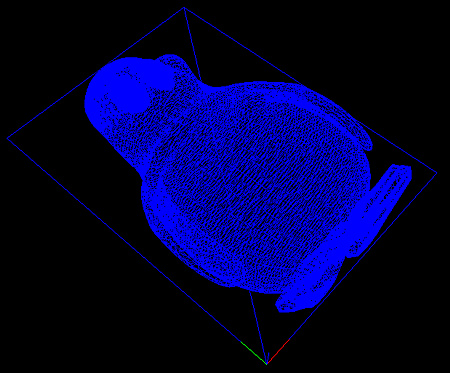
Together with another Anders (from Sweden) I've worked a little bit on some C# code for rendering stuff in OpenGL. The idea is to put together a basic framework where CAD/CAM ideas and algorithms can be tested. Above one of the first useful screenshots where I've rendered an STL file with about 22k triangles.

The code needs to be cleaned up and made all object-oriented and nice, but after that it should not be hard to test the Drop-Cutter algorithm and generate some raster-finish paths.

I've also been reading a 2004 paper by Yau et al. which explains the drop-cutter algorithm for an APT tool. I'm not very interested in the tapered cutters - but that can be added later if needed. What's more interesting in the paper is a kd-tree approach for finding out which triangles are under the 'shadow' of the cutter.

The idea is that it's not necessary to test against all triangles, only those that are under the cutter. Since the circular cutter and the triangles are differently shaped, Yau et al. start by approximating both cutter and triangles with rectangles. So they generate rectangular bounding boxes around each triangle and also around the cutter. The task then is for a given position of the cutter to find which bounding-boxes(triangles) intersect it. I understand this is a variant of what's called an orthogonal range search in computer science.

If anyone with a good understanding of kd-trees and/or range-searching is willing to help with a C# implementation I'd be glad to send over the Yau et al. pdf!

Drop Cutter 3/3: Edge Test

The third and final test in the drop cutter algorithm is to drop the cutter down so it touches an edge. The vertex and facet tests were quite easy, but this one requires a bit of calculations. I'm following Chuang2002.
To simplify things we first translate the tool in the (x, y) plane to (0, 0), and then rotate the edge we are testing against so that it lies along the x-axis and is below the cutter (or on top of the x-axis). The distance from the edge to (0, 0) is l.

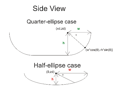
Now we imagine a vertical plane through the edge and slice the cutter with that plane. There are two cases, depending on l.

If R-r>l we are cutting with a plane (green) that results in an intersection that has two quarter ellipses at the sides and a flat part in the middle. These ellipses have centers with
xd = +/- sqrt( (R-r)^2 - l^2 )

The other case is shown with a red line: if
R-r<=l<R
the intersection of the cutter will be a half ellipse centered at xd=0.
In both cases the curved part of the intersection is described by
f(theta) = (w*cos(theta) , h*cos(theta) ) where 0<theta<pi
h and w, the height and width of the ellipse are given by

  • quarter-ellipse case:
    • h=r
    • w=sqrt(R^r - l^2) - sqrt( (R-r)^2 - l^2 )
  • half -ellipse case:
    • h=sqrt( r^2 -(l-(R-l))^2 )
    • w=sqrt(R^2-l^2)

Now that the geometry is clear we can have the edge contact the intersection. That happens at a point where the tangents("slopes") are equal. A tangent vector to the ellipse is given by
f'(theta) = (-w*sin(theta) , -h*cos(theta) )
which can be equated with the slope of the line:
w*sin(theta) / h*cos(theta) = (x1-x2)/(z1-z2)
and we find the angle theta of our CC point:
theta = atan( h*(x1-x2)/w*(z1-z2))
(z1=z2 is a trivial special case not handled here)

The CC point is now given by
xc = xd +/- abs(w*cos(theta))
which should be checked if it lies between x1 and x2. If it does we are contacting the edge, and we can calculate the z-coordinate of the CC point as:
zc = ((xc-x1)/(x2-x1))*(z2-z1) +z1
and finally that leads us to the correct cutter height
ze = zc + abs(h*sin(theta)) - r

Now I need to put all these tests together and find a way of importing STL files into matlab. That way I can begin to test if/how my drop cutter algorithm works!

There's still a lot to do before I have a set of algorithms for basic 3-axis toolpath creation: "push-cutter" a 2D version of drop cutter, 2D line/arc? offsets, zigzag paths, STL-slice with plane, z-buffer simulation of stock material, to name a few things...

Offset Ellipse

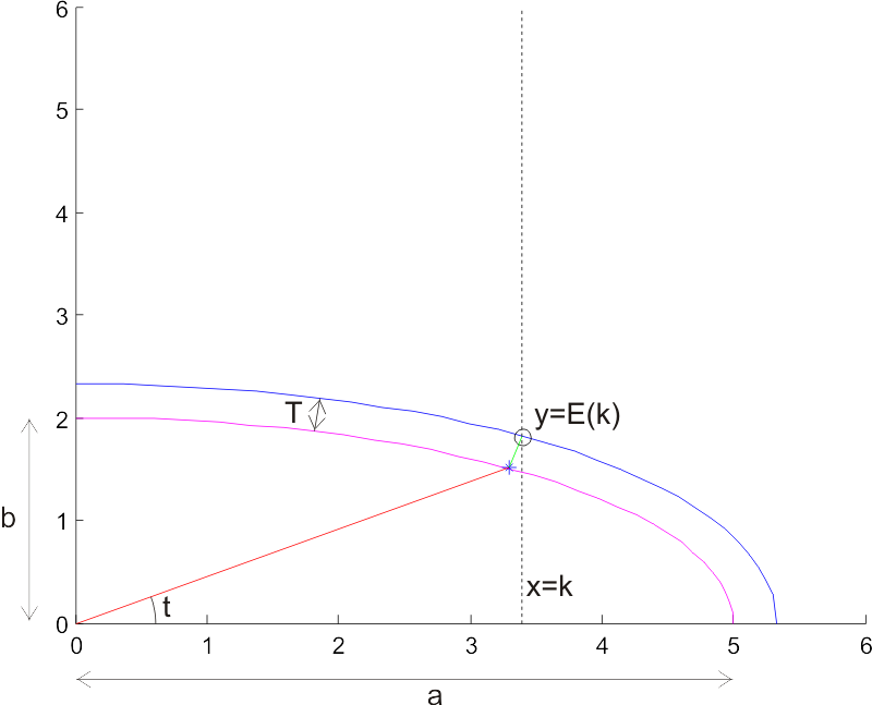
Continuing with some random thoughts on CAM algorithms, here's a diagram I drew in response to a question on offset ellipses posed by Julian Todd.

(click image for high-resolution version)
The task is to find an offset ellipse to a given ellipse (magenta). The offset ellipse (blue) should lie a distance T, measured along the normal to the ellipse (I've drawn one normal of length T in green), from the original ellipse. Drawing the offset ellipse is simple, but it's a bit harder to find a point on the offset for a given x-coordinate x=k. I've marked this point with a circle, and its coordinates are (k, E(k)), so E(k) is a function that returns the sought y-coordinate.

I took Julian's advice of using a numerical method with respect to the geometry (not neccessarily cartesian coordinates), and parametrized the ellipse as a function of an angle t. So points along the ellipse lie at:

ex=a*cos(t)
ey=b*sin(t)

Where a and b are the major and minor axes of the ellipse, and t is an angle between 0 and 2pi. At every point there's a normal vector

nx = b*cos(t)
ny = a*sin(t)

To find points on the sought offset ellipse, we need to scale this normal so it's length is T. Each normal has a length

l=sqrt(nx^2 + ny^2)

So the sought normal vector is

nx_T = (nx/l)*T
ny_T = (ny/l)*T

or more explicitly

nx_T = ( b*cos(t) / sqrt((b*cos(t) )^2 + (a*sin(t))^2) ) * T
ny_T = ( a*sin(t) / sqrt((b*cos(t) )^2 + (a*sin(t))^2) ) * T

Now, points on the offset ellipse lie at

oe_x = ex + nx_T
oe_y = ey + ny_T

and we need to find the particular t angle which results in a point (oe_x, oe_y) for which oe_x = k holds. Inserting the above expressions, this happens when:

(a+T*b/sqrt( ( b*cost(t) )^2 + ( a*sin(t) )^2 ))*cos(t) -k = 0

I haven't looked for an analytic solution to this equation, but plotting it for a few test cases seems to indicate that it's fairly 'benign', and Matlab's fzero function finds a solution very quickly. If we call the solution to this equation tk, the sought point on the offset ellipse is

E(k) = oe_y(tk)

Here are two Matlab scripts I used to plot this figure: ellipsetest.m is the main program, and oe.m is used when solving the equation.