For the simple 'one-inch-photodetector' with a Hamamatsu S5973 photodiode, OPA657 op-amp, and 10 kOhm feedback-resistor the predicted noise-floor and signal output is fairly easy to compute, from a simplified schematic like this:
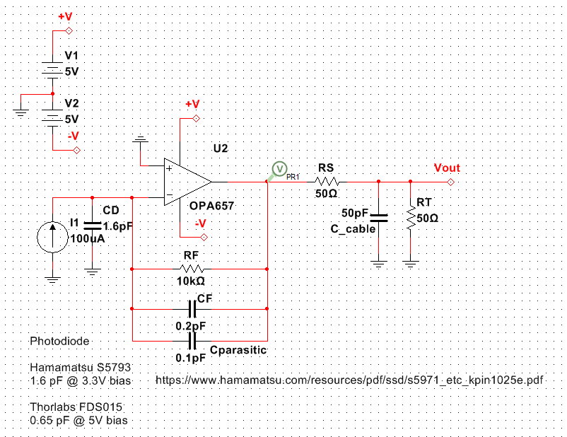
The photodiode is modeled as a current-source and adds some source-capacitance (in addition to the op-amp input capacitance). The board and components have some parasitic capacitance over RF, and additionally CF is chosen large enough for stability (no self-oscillation). A 50-ohm series resistor couples the signal into a coax to the spectrum-analyzer or scope.
For some (yet unknown..) reason I need to dial-down the GBWP of the op-amp to about half the datasheet value of 1.6 GHz - only then do I get good agreement between the predicted and measured spectra:
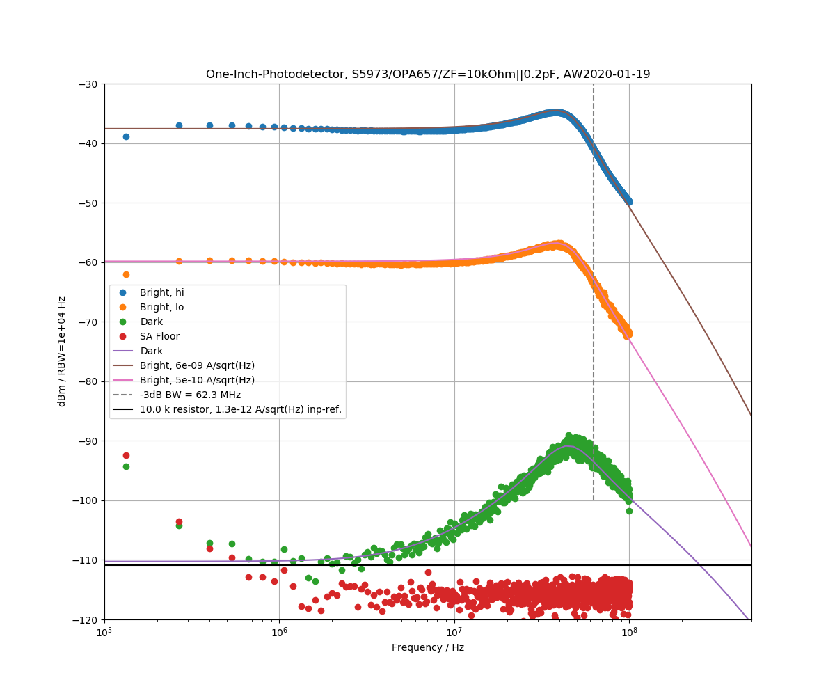
Ideally we'd want the dark-noise to be close to the thermal/Johnson noise of RF (like it, roughly, is at <10 MHz), but the circuit has a noise-peak as the -3dB bandwidth is approached. The 'bright' detector response was measured by shining light from a VCSEL onto the detector and modulating the laser with the TG output from the spectrum analyzer. Moving the divergent laser source closer or further away from the detector adjusts the signal level.
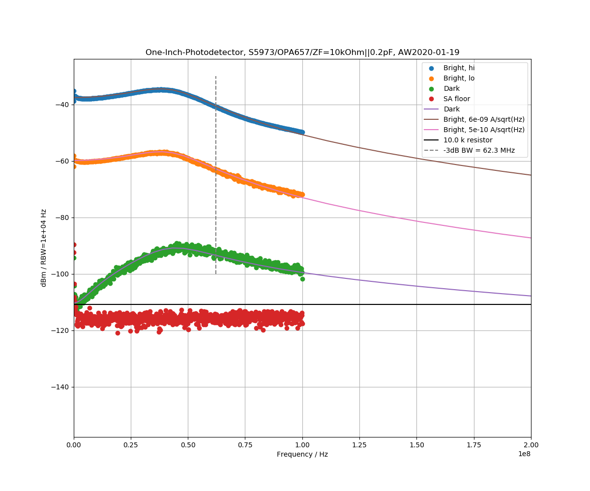
Here is the same plot with linear frequency scale.