This small PCB is going to sit between the M5i20 optoisolators and the VFD that runs the spindle on the mill.
Starting from the lower edge of the card there are three outputs that drive optoisolators on the VFD through BC337 transistors. On the VFD they are wired to Forward Start/Stop, Reverse Start/Stop, and External Fault.
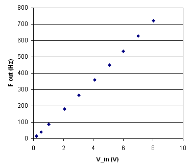
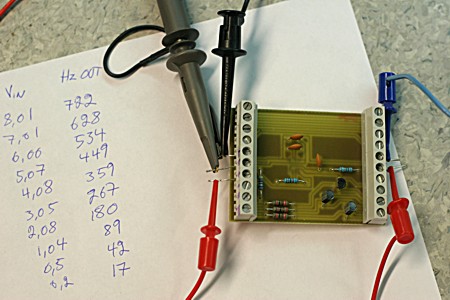
The next signal goes in the opposite direction, from VFD to EMC. The VFD has a general purpose analog output which can be programmed to monitor motor current, power, etc. Since the m5i20 doesn't have analog inputs I'm using the V-2-f converter AD654. It's hidden below the board since it was only available in surface mount. As seen below it seems to work nicely. I designed the output to be at 1000 Hz with 10V input, but I'm only supplying 12 V to the AD654 which means the output goes all funny somewhere after 8 V input. Maybe the VFD software can scale the 0-10V output, or I can put a voltage divider in front of the AD654 to get maximum 8 V input. I need to come up with a HAL config that reads a general purpose IO pin and figures out the frequency (think big green/red pyVCP spindle load meter in AXIS).
The top two connections are for the frequency reference, a pulse train, and for an NC E-stop relay.
This card together with a spindle encoder should allow for rigid-tapping.