Now the problem of contacting a toroidal cutter with the facet of a triangle.
We need to find the equation of the plane which contains the triangle. If the triangle is defined by three points p1 = (x1, y1, z1), p2 = (x2, y2, z2), p3 = (x3, y3, z3) then a surface normal will be perpendicular to both p1-p2 and p1-p3:
N = (NX, NY, NZ) = (p1-p3)x(p1-p2)
and it can be normalized to unit length by setting
n = (nx, ny, nz) = N / sqrt(NX^2 + NY^2 + NZ^2)
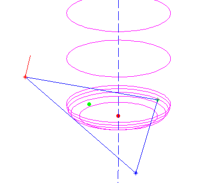
I've drawn a surface normal in red in the picture above.
Now the plane containing the triangle is given by
a x + b y + c z + d = 0
where (a, b, c) = (nx, ny, nz) and d can be found by noting that any of the points p1, p2, or p3 must satisfy the equation:
d = - nx*x1 -ny*y1 -nz*z1
the plane is going to make an angle theta with any vertical line, where theta = asin(c)
Then we need a new figure:
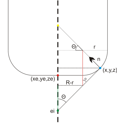
We start out at ei = (xe, ye, zi) , the point on the plane that intersects the line along which we're dropping the cutter (green dot above). It needs to satisfy the equation for the plane, so
zi = - (d + a xe + b ye) / c
Note: c=0 is a special case which needs to be handled separately.
from here we need to climb up to the correct ze, and that's done by first summing the green distance, then the red one, and then dropping down by r:
ze = - (d + a xe + b ye) / c + (R-r)/tan(theta) + r/sin(theta) - r
Now we have the cutter in contact with the plane, but we still need to check that the cutter contact point (CC-point, the blue dot above) is within the triangle facet and not some other point on the plane. To do that we need (x,y,z): If we start at the red point e = (xe, ye, ze) we get to he CC point by travelling upwards to the yellow point, and then along the normal down to the CC point:
CC = e + ( (R-r)*tan(theta)+r )k - ( (R-r)/cos(theta) +r )n
where k=(0, 0, 1) is a unit vector along the positive z-axis.
All of this seems to work as evidenced by the top picture where a toroidal cutter is brought into contact with a facet. The CC point is indicated with a green dot, and the CL (cutter location, or (xe, ye, ze)) point with a red dot.
Now we need to check if the CC point lies within the triangle, but that will have to wait until the next post... (Mr. Todd has some thoughts on this)
Cool articles. Are you working on a CAM software?
But wouldn't a brute force approach be a sensible solution with today's computing power? Just draw depth maps of cutters and machined model with adequate resolution (1µm grid?). Then just compare them point by point to ensure that they stay within allowed depth. Cutter map could be used to "eat" the model map so it would be easy to figure out the rest material.
Uhm.. A quick calculation revealed that 1µm grid would be a quite memory hungry. But could work for small parts.
Hi Tero!
First I am trying to understand the basic CAM algorithms. That involves testing them and playing with them in MATLAB. Then I think I will try to implement them in some language. It probably make sense to use C, but call the C-functions and do graphics etc. in Python.
After that we'll see if there is enough interested open source developers to really build a working GUI around the algorithms. I'm not particularly good at OpenGL or GUI programming. CAD file import (DXF, IGES, etc etc) is another major thing which I don't find particularly thrilling to program.
As you noted the brute-force thing eats up a lot of memory. So does triangulated surfaces, but I think they are the industry standard currently. That would be another major thing for a working CAM system: everything except points, lines, arcs, and triangles will have to be tessellated into those primitives(at some given resolution).
For a cutting simulation you would use exactly the type of model you describe, a forest of 'match-sticks' standing up along the z-axis and being shortened to the proper length wherever the cutter travels. I understand the Freesteel stock model works like this, but it is somehow adaptive so you use a dense grid of match-sticks where you need them, and less sticks in flat areas.
In addition to this drop-cutter stuff the other major thing that is needed for basic CAM functionality is 2D curve offset. With those two basic algorithms I think we can create most toolpaths that we have used on our mill. I don't think adaptive stuff and 'intelligent' complex 3D paths are needed to make a first open source CAM package that would still be popular among users.
Anders
Anders,
I am learning a lot from the code you have written. I am going to assume this project has been left on hiatus. I might OPENSOURCE my CAM project soon. It's built from scratch in Objective-C and it's 100% Mac.
I would like to invite you to join in working on it, but I am trying to come up with a 4 and 5 axis only approach. Remember that as far as CNC goes, an indexer or trunnion changes the game completely. If you want to talk about more of this, email me.
Best,
Julian
Hi Julian,
I haven't worked on opencamlib (3D cutter projection) or openvoronoi (2D pocketing) for a while. The latest code is available on github. There is no GUI and there seems to be little interest in developing one in the community.
There's been some recent work with a CAM-module for FreeCAD, but I haven't heard or seen the latest developments.
Do post a link to your source-code, screenshots, or videos if/when you release something!
Anders
Hi Anders,
That was supposed to be one of the easy ones but it is giving more trouble than the two other tests. As soon as the normal z-axis value goes below 0.05 or so I start getting imposible (too tall) zi values.
Do you have any idea what I might be missing?
Thanks,
misan
Hi Miguel,
check out these 23 lines of code in opencamlib:
https://github.com/aewallin/opencamlib/blob/master/src/cutters/millingcutter.cpp#L50
I can't remember the details, but there seems to be a special case for horizontal or nearly horizontal facets.
Fixed, it was my isInside code what was wrong 🙁