I wasn't entirely happy with my frequency distribution amplifier prototype measurements, so I decided to do some SPICE simulations.
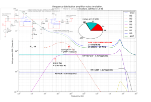
Here is a circuit close to the original TADD-1 design, configured for a voltage gain of 2, which when loaded with 50R corresponds to unity gain or 0 dB.
The main contribution to the noise floor at 10 MHz is by the AD8055 op-amp (roughly 3/4ths), with the gain-resistors R4 and R5 also contributing (roughly 1/4th). The simulation gives an output-referred noise-floor of 17.4 nV/sqrt(Hz) between around 100kHz and 20MHz. At low frequencies the 1/f noise of the op-amp dominates. The large 47k bias-resistors R2 and R3 are not bypassed/filtered in this design and they contribute significantly at low frequencies.
17.4nV/sqrt(Hz) is -142 dBm/Hz. This is a one-sided spectrum so we subtract 3 dB to get a single-sideband number, and then another 3 dB since noise is divided equally into AM and PN. This gives a best-case PN of -148 dBc/Hz for a 0 dB input/output power. In my measurements I got about -157 dBc/Hz with +7 dBm output.
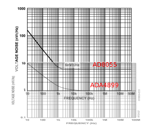
The v2 design uses the ADA4899-1 op-amp instead of the AD8055. This improves the op-amp input voltage noise floor from 6 nV/sqrt(Hz) to 1 nV/sqrt(Hz) while also reducing the near-DC voltage noise by more than ten-fold.
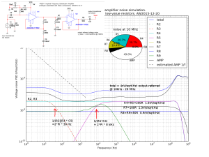
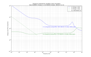
The simulation for the ADA4899-1 design shows an output-referred noise floor of 4 nV/sqrt(Hz) from 10 kHz to 20 MHz. This corresponds to about -155 dBm/Hz, a 12.7 dB improvement over the original design. The SPICE model for the ADA4899-1 does not include 1/f noise so I have estimated it with a dashed line. I have tried to minimize the resistor noise with reduced resistance values for the gain-setting resistors R4, R5, and a bypassed (C5) 'T'-circuit for the DC-bias (R2, R3, R9).
The theoretical PN floor with 0 dBm signal is now -161 dBc/Hz (again 13 dB better than for the original design).
Here is a figure that compares the two simulations:
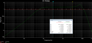
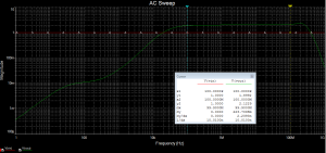
These figures show an AC sweep response for the SPICE simulations:
Further ideas and ToDo:
- What is the limit for reducing values of R4 and R5? Power-dissipation, current-draw from the op-amp?
- Reduce value of R7 - do we even need it.. (improves isolation between output stages?)
- Replace R9 with an inductor - BUT it creates a resonance with C5 that needs to be damped - probably not worth it.
- Improve on the powersupply schematic in the prototype. Spurs were big with a SMPS +12VDC supply.
- Do PSRR simulations? Does that give different optimization goals for the DC-bias circuit?
- Find an even better op-amp?
- Where do we find a good SPICE model for ADA4899-1? The one I am using has a realistic AC gain response but unrealistic noise model near DC. There is an alternative on the analog.com website with realistic 1/f noise behaviour but infinite AC gain bandwidth!!??
Constructive comments are welcome!
I can't understand why you are not so happy, but I think...
>What is the limit for reducing values of R4 and R5? Power-dissipation, current-draw from the op-amp?
Mainly, these are limited by the output current driving ability of the op-amp. If the limit is violated, the current limiter will work and the distortion will increase.
>Reduce value of R7 - do we even need it.. (improves isolation between output stages?)
In the case of ADA4899, you need a series resistor(24.9 Ω) when you want to use it with unity gain.
>Replace R9 with an inductor - BUT it creates a resonance with C5 that needs to be damped - probably not worth it.
I recommend you to use these amps with a bipolar voltage supply. Because these high-speed amps are designed to perform best under a bipolar voltage supply.
>Improve on the powersupply schematic in the prototype. Spurs were big with a SMPS +12VDC supply.
SMPS = switch mode power supply? If so, it's a little bit crazy to use those for low-noise amplifiers. I recommend you to use linear power supplies.
>Do PSRR simulations? Does that give different optimization goals for the DC-bias circuit?
Please refer to the
http://www.analog.com/media/en/technical-documentation/data-sheets/ADA4899-1.pdf
Fig.35 at pp.11. In general, op-amp's PSRR (and CMRR) becomes quite worse at high frequencies. This is one of the reason why you can't use switching power supplies for low-noise amplifiers.
>Find an even better op-amp?
Maybe, 1nV/√Hz is quite low noise. You need more? Maybe, you must use liquid nitrogen :-).
And I think that the case or chassis is the part of low-noise amplifier. You need evaluate your circuit with those.
LT3042 was suggested as a better voltage regulator.
>LT3042 was suggested as a better voltage regulator.
LT3042's output current limit is 200mA, and you may need 2 or more LT3042s if you want to drive 8ch 50Ω-lines.